Chapter 7 Maintaining the Cisco Catalyst 5500 Multiswitch Router
Replacing Hardware Components
Avoiding Problems When Inserting and Removing Modules
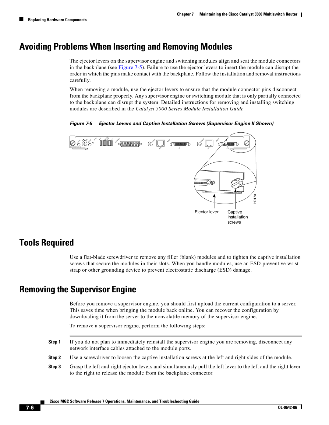
The ejector levers on the supervisor engine and switching modules align and seat the module connectors in the backplane (see Figure
When removing a module, use the ejector levers to ensure that the module connector pins disconnect from the backplane properly. Any supervisor engine or switching module that is only partially connected to the backplane can disrupt the system. Detailed instructions for removing and installing switching modules are described in the Catalyst 5000 Series Module Installation Guide.
Figure 7-5 Ejector Levers and Captive Installation Screws (Supervisor Engine II Shown)
STATUS
SUPERVISOR ENGINE
FAN PS2 PS1
ACTIVE | RESET | 100% |
|
|
SWITCHLOAD
1%
CONSOLE![]()
100 | MBPS |
|
|
|
| ||
|
|
| |
LINK |
|
| |
MDI | X | ||
|
|
| |
PORT | 1 |
|
A411
100 | MBPS |
| |
LINK | |
MDI | X |
|
PORT | 2 |
|
A411
H9170
Ejector lever | Captive |
| installation |
| screws |
Tools Required
Use a
Removing the Supervisor Engine
|
|
|
| Before you remove a supervisor engine, you should first upload the current configuration to a server. | |
|
|
|
| This saves time when bringing the module back online. You can recover the configuration by | |
|
|
|
| downloading it from the server to the nonvolatile memory of the supervisor engine. | |
|
|
|
| To remove a supervisor engine, perform the following steps: | |
|
|
|
|
| |
|
|
| Step 1 | If you do not plan to immediately reinstall the supervisor engine you are removing, disconnect any | |
|
|
|
| network interface cables attached to the module ports. | |
|
|
| Step 2 | Use a screwdriver to loosen the captive installation screws at the left and right sides of the module. | |
|
|
| Step 3 | Grasp the left and right ejector levers and simultaneously pull the left lever to the left and the right lever | |
|
|
|
| to the right to release the module from the backplane connector. | |
|
|
| Cisco MGC Software Release 7 Operations, Maintenance, and Troubleshooting Guide | ||
|
|
| |||
|
|
|
|
|
|
|
|
|
| ||
|
|
|
| ||