Chapter 7 Maintaining the Cisco Catalyst 5500 Multiswitch Router
Replacing Hardware Components
Note You can insert and remove the Flash memory card with the power on.
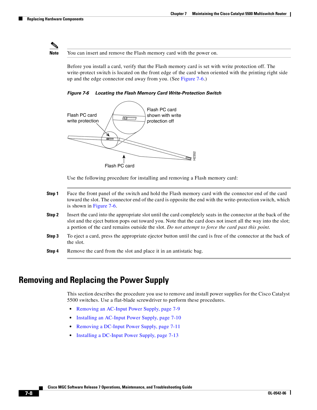
Before you install a card, verify that the Flash memory card is set with write protection off. The
Figure 7-6 Locating the Flash Memory Card Write-Protection Switch
| Flash PC card |
Flash PC card | shown with write |
write protection | protection off |
H2352
Flash PC card
Use the following procedure for installing and removing a Flash memory card:
Step 1 Face the front panel of the switch and hold the Flash memory card with the connector end of the card toward the slot. The connector end of the card is opposite the end with the
Step 2 Insert the card into the appropriate slot until the card completely seats in the connector at the back of the slot and the eject button pops out toward you. Note that the card does not insert all the way into the slot; a portion of the card remains outside the slot. Do not attempt to force the card past this point.
Step 3 To eject a card, press the appropriate ejector button until the card is free of the connector at the back of the slot.
Step 4 Remove the card from the slot and place it in an antistatic bag.
Removing and Replacing the Power Supply
This section describes the procedure you use to remove and install power supplies for the Cisco Catalyst 5500 switches. Use a
•Removing an
•Installing an
•Removing a
•Installing a
Cisco MGC Software Release 7 Operations, Maintenance, and Troubleshooting Guide
| ||
|