Chapter 7 Maintaining the Cisco Catalyst 5500 Multiswitch Router
Replacing Hardware Components
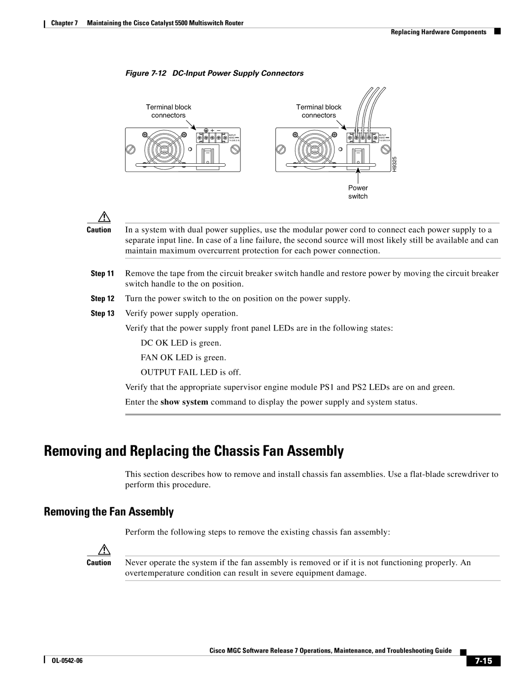
Figure 7-12 DC-Input Power Supply Connectors
Terminal block | Terminal block |
connectors | connectors |
| INPUT |
| 48/60 |
| 14.0/8.0 A |
Power switch
INPUT 48/60 14.0/8.0 A
H9325
Caution In a system with dual power supplies, use the modular power cord to connect each power supply to a separate input line. In case of a line failure, the second source will most likely still be available and can maintain maximum overcurrent protection for each power connection.
Step 11 Remove the tape from the circuit breaker switch handle and restore power by moving the circuit breaker switch handle to the on position.
Step 12 Turn the power switch to the on position on the power supply.
Step 13 Verify power supply operation.
Verify that the power supply front panel LEDs are in the following states:
DC OK LED is green.
FAN OK LED is green.
OUTPUT FAIL LED is off.
Verify that the appropriate supervisor engine module PS1 and PS2 LEDs are on and green.
Enter the show system command to display the power supply and system status.
Removing and Replacing the Chassis Fan Assembly
This section describes how to remove and install chassis fan assemblies. Use a
Removing the Fan Assembly
Perform the following steps to remove the existing chassis fan assembly:
Caution Never operate the system if the fan assembly is removed or if it is not functioning properly. An overtemperature condition can result in severe equipment damage.
Cisco MGC Software Release 7 Operations, Maintenance, and Troubleshooting Guide
|
| ||
|
|