Chapter 7 Maintaining the Cisco Catalyst 5500 Multiswitch Router
Replacing Hardware Components
Step 2 Turn the power switch to the OFF (0) position on the power supply you are removing (see Figure
Step 3 Remove the two screws securing the terminal block cover and slide the cover straight off the terminal block (see Figure
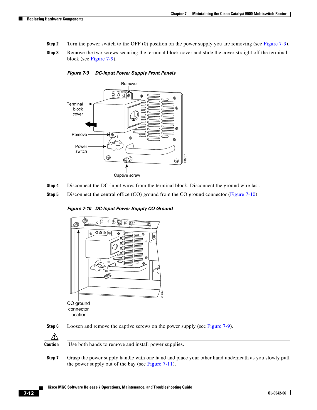
Figure 7-9 DC-Input Power Supply Front Panels
Remove
DC FAN
OUTPUT![]()
OK | OK | FAIL |
Terminal ![]() block cover
block cover
Remove
Power switch
![]()
![]() I
I
0
H8767
Captive screw
Step 4 Disconnect the
Figure 7-10 DC-Input Power Supply CO Ground
SWITCH/PROCESSOR
FAN | RESET | TX |
|
|
|
PS2 |
| 2 |
| ||
RX |
| SLOT |
| ||
PS1 |
|
|
| ||
|
| LINK |
| SLOT |
|
|
|
| Enet | PCMCIA | EJECT |
|
|
|
|
o
o![]()
28649
CO ground
connector
location
Step 6 Loosen and remove the captive screws on the power supply (see Figure
Caution Use both hands to remove and install power supplies.
Step 7 Grasp the power supply handle with one hand and place your other hand underneath as you slowly pull the power supply out of the bay (see Figure
Cisco MGC Software Release 7 Operations, Maintenance, and Troubleshooting Guide
| ||
|