Chapter 7 Maintaining the Cisco Catalyst 5500 Multiswitch Router
Replacing Hardware Components
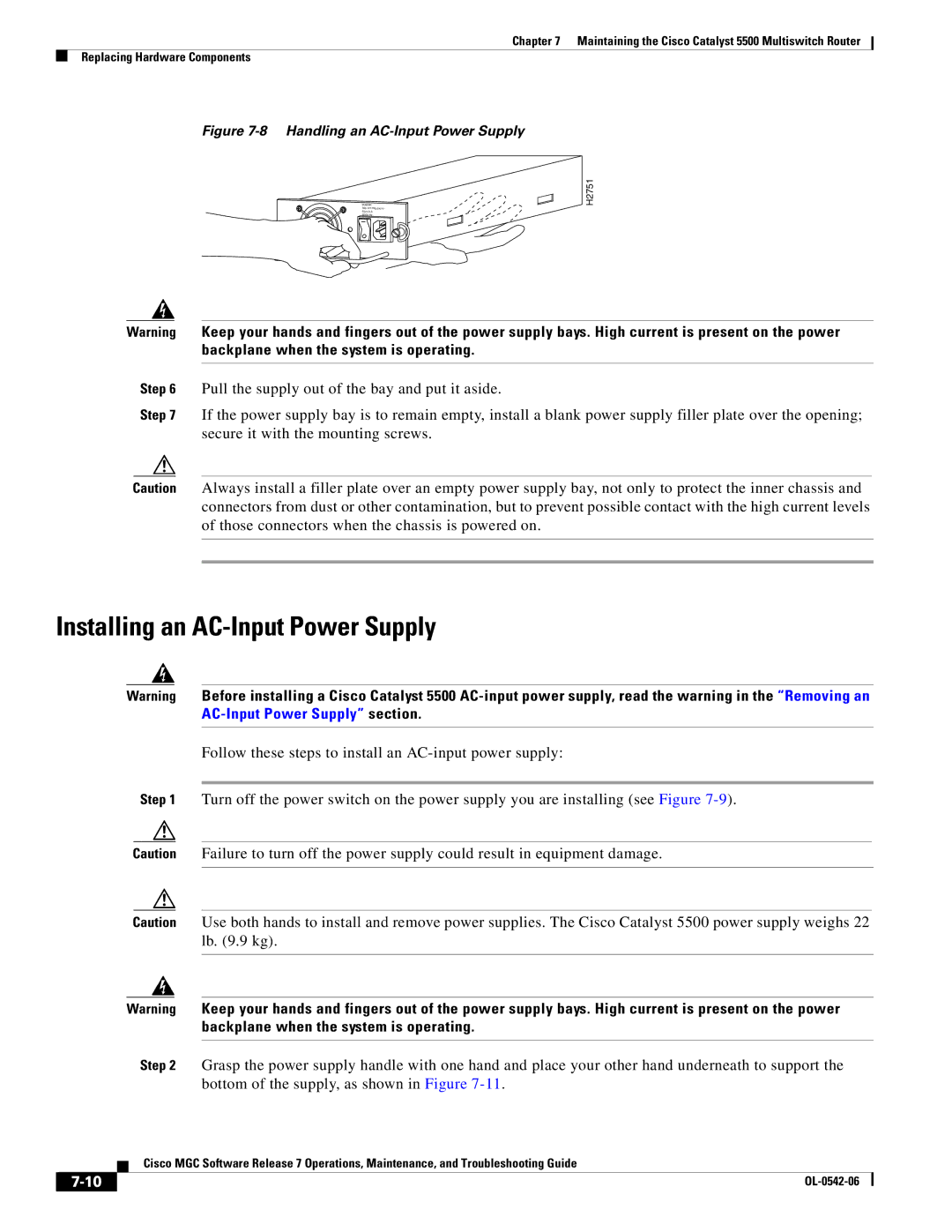
Figure 7-8 Handling an AC-Input Power Supply
POWER
H2751
Warning Keep your hands and fingers out of the power supply bays. High current is present on the power backplane when the system is operating.
Step 6 Pull the supply out of the bay and put it aside.
Step 7 If the power supply bay is to remain empty, install a blank power supply filler plate over the opening; secure it with the mounting screws.
Caution Always install a filler plate over an empty power supply bay, not only to protect the inner chassis and connectors from dust or other contamination, but to prevent possible contact with the high current levels of those connectors when the chassis is powered on.
Installing an AC-Input Power Supply
Warning Before installing a Cisco Catalyst 5500
Follow these steps to install an
Step 1 Turn off the power switch on the power supply you are installing (see Figure
Caution Failure to turn off the power supply could result in equipment damage.
Caution Use both hands to install and remove power supplies. The Cisco Catalyst 5500 power supply weighs 22 lb. (9.9 kg).
Warning Keep your hands and fingers out of the power supply bays. High current is present on the power backplane when the system is operating.
Step 2 Grasp the power supply handle with one hand and place your other hand underneath to support the bottom of the supply, as shown in Figure
Cisco MGC Software Release 7 Operations, Maintenance, and Troubleshooting Guide
| ||
|