ACIP Installation Prerequisites
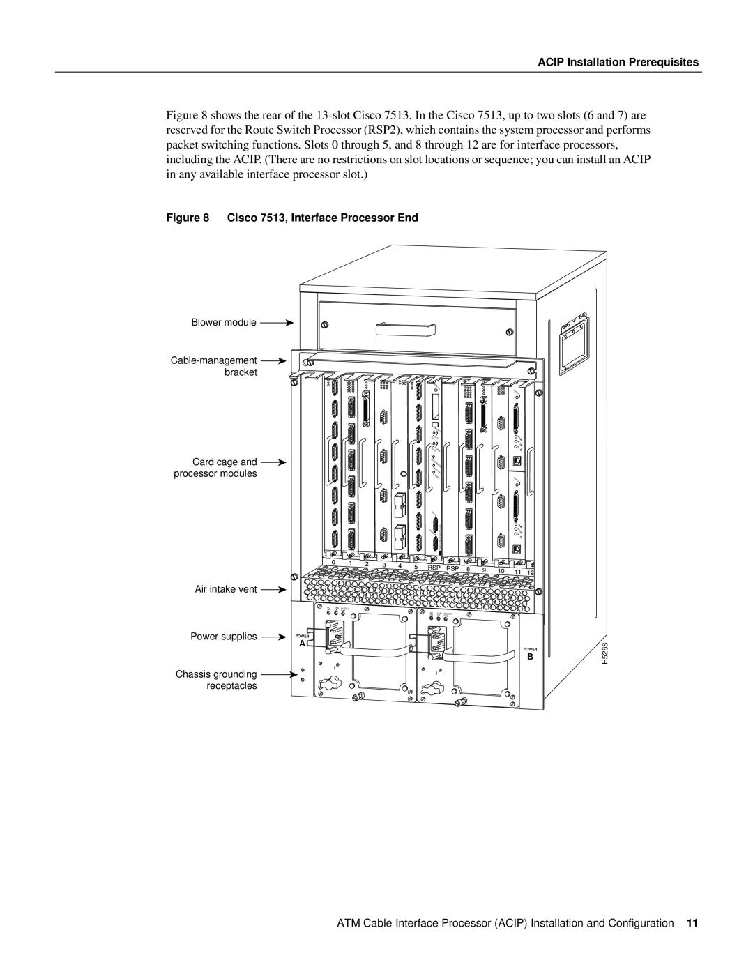
Figure 8 shows the rear of the 13-slot Cisco 7513. In the Cisco 7513, up to two slots (6 and 7) are reserved for the Route Switch Processor (RSP2), which contains the system processor and performs packet switching functions. Slots 0 through 5, and 8 through 12 are for interface processors, including the ACIP. (There are no restrictions on slot locations or sequence; you can install an ACIP in any available interface processor slot.)
Figure 8 Cisco 7513, Interface Processor End
Blower module ![]()
![]() bracket
bracket
Card cage and ![]() processor modules
processor modules
Air intake vent ![]()
AC | FAN | OUTPUT |
OK | OK | FAIL |
Power supplies | POWER |
| A |
Chassis grounding | I |
| |
receptacles | 0 |
|
NORMAL |
|
|
|
| ENABLE |
EJECT |
| |
SLOT | 1 |
|
SLOT0 |
| |
SLAVEMASTER |
| |
SLAVE/MASTER |
| |
CPU | HALT |
|
|
| |
RESET | ENABLE | |
|
| |
AUX. |
|
|
CONSOLE | ROUTE | |
SWITCHPROCESSOR2 | ||
|
AC | FAN | OUTPUT |
OK | OK | FAIL |
POWER
B
I
0
H5268
ATM Cable Interface Processor (ACIP) Installation and Configuration 11