Installing and Removing an ACIP
Installing and Removing an ACIP
An ACIP slides into slots in the rear of a Cisco 7500 series chassis and connects directly to the backplane. The backplane slots are keyed so that the ACIP can be installed only in the slots designated for it. (For interface processor slot locations, refer to section “Hardware and Host Router Prerequisites” on page 9.) Figure 9 shows the procedures for removing and installing an ACIP. When tightened, the captive installation screws on the ends of the ACIP faceplate help ensure proper seating in the backplane. After using the ejector levers to install an ACIP, immediately tighten the captive installation screws to prevent an ACIP from becoming partially dislodged from the backplane, and before installing additional processors; this will help reduce the effects of EMI.
Caution Failure to use ejector levers could result in a partial backplane connection, which can hang the system.
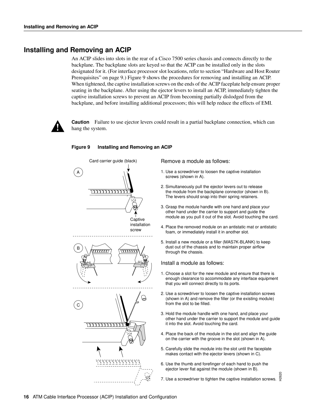
Figure 9 Installing and Removing an ACIP
Card carrier guide (black)
A
Captive installation screw
B
C
Remove a module as follows:
1.Use a screwdriver to loosen the captive installation screws (shown in A).
2.Simultaneously pull the ejector levers out to release the module from the backplane connector (shown in B). The levers should snap into their spring retainers.
3.Grasp the module handle with one hand and place your other hand under the carrier to support and guide the module as you pull it out of the slot. Avoid touching the card.
4.Place the removed module on an antistatic mat or antistatic foam, or immediately install it in another slot.
5.Install a new module or a filler
Install a module as follows:
1.Choose a slot for the new module and ensure that there is enough clearance to accommodate any interface equipment that you will connect directly to its ports.
2.Use a screwdriver to loosen the captive installation screws (shown in A) and remove the filler (or the existing module) from the slot to be filled.
3.Hold the module handle with one hand, and place your
other hand under the carrier to support the module and guide it into the slot. Avoid touching the card.
4.Place the back of the module in the slot and align the guide on the carrier with the groove in the slot (shown in A).
5.Carefully slide the module into the slot until the faceplate makes contact with the ejector levers (shown in C).
6.Use the thumb and forefinger of each hand to push the ejector lever flat against the module (shown in B).
7.Use a screwdriver to tighten the captive installation screws. H2620
16ATM Cable Interface Processor (ACIP) Installation and Configuration