ACIP Description
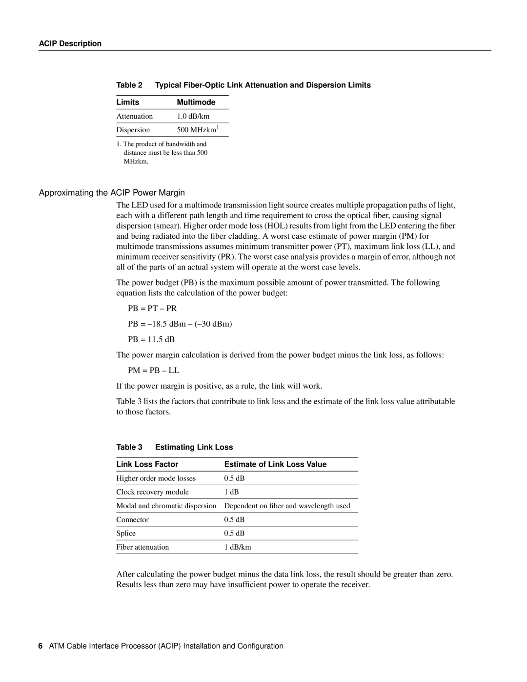
Table 2 Typical
Limits | Multimode |
Attenuation | 1.0 dB/km |
|
|
Dispersion | 500 MHzkm1 |
1.The product of bandwidth and distance must be less than 500 MHzkm.
Approximating the ACIP Power Margin
The LED used for a multimode transmission light source creates multiple propagation paths of light, each with a different path length and time requirement to cross the optical fiber, causing signal dispersion (smear). Higher order mode loss (HOL) results from light from the LED entering the fiber and being radiated into the fiber cladding. A worst case estimate of power margin (PM) for multimode transmissions assumes minimum transmitter power (PT), maximum link loss (LL), and minimum receiver sensitivity (PR). The worst case analysis provides a margin of error, although not all of the parts of an actual system will operate at the worst case levels.
The power budget (PB) is the maximum possible amount of power transmitted. The following equation lists the calculation of the power budget:
PB = PT – PR
PB =
PB = 11.5 dB
The power margin calculation is derived from the power budget minus the link loss, as follows:
PM = PB – LL
If the power margin is positive, as a rule, the link will work.
Table 3 lists the factors that contribute to link loss and the estimate of the link loss value attributable to those factors.
Table 3 Estimating Link Loss
Link Loss Factor | Estimate of Link Loss Value |
Higher order mode losses | 0.5 dB |
|
|
Clock recovery module | 1 dB |
|
|
Modal and chromatic dispersion | Dependent on fiber and wavelength used |
|
|
Connector | 0.5 dB |
|
|
Splice | 0.5 dB |
|
|
Fiber attenuation | 1 dB/km |
|
|
After calculating the power budget minus the data link loss, the result should be greater than zero. Results less than zero may have insufficient power to operate the receiver.
6ATM Cable Interface Processor (ACIP) Installation and Configuration