VIP2 and the 4R Port Adapter
Caution To prevent interface reconfiguration requirements, you should replace a port adapter with the same type of port adapter you removed, but this is not a requirement.
When only one port adapter is installed on a VIP2, a blank port adapter must fill the empty slot to allow the VIP2 and router chassis to conform to electromagnetic interference (EMI) emissions requirements, and so that air flows through the chassis properly. If you plan to install a new port adapter, you must first remove the blank port adapter.
Use the following standard procedure to remove and replace any type of port adapter on a VIP2:
Step 1 Attach an
Note If you want to install a new port adapter on a VIP2 with a single port adapter, you must first remove the blank port adapter from the port adapter slot in which you want to install the new port adapter.
Step 2 For a new port adapter installation or a port adapter replacement, disconnect any interface cables from the ports on the front of the port adapter, although, this is not required. You can remove VIP2s with cables attached; however, we do not recommend it.
Step 3 Remove the VIP2 from the system. (Follow the steps in the section “Removing a VIP2” in the configuration note
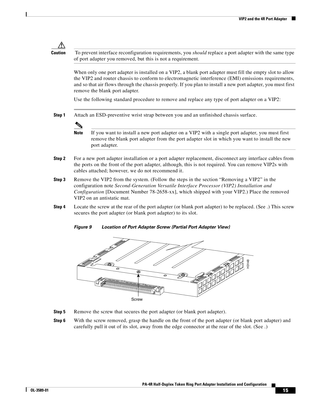
Step 4 Locate the screw at the rear of the port adapter (or blank port adapter) to be replaced. (See .) This screw secures the port adapter (or blank port adapter) to its slot.
Figure 9 Location of Port Adapter Screw (Partial Port Adapter View)
H3148
Screw
Step 5 Remove the screw that secures the port adapter (or blank port adapter).
Step 6 With the screw removed, grasp the handle on the front of the port adapter (or blank port adapter) and carefully pull it out of its slot, away from the edge connector at the rear of the slot. (See .)
| 15 |
| |
|
|