VIP2 and the 4R Port Adapter
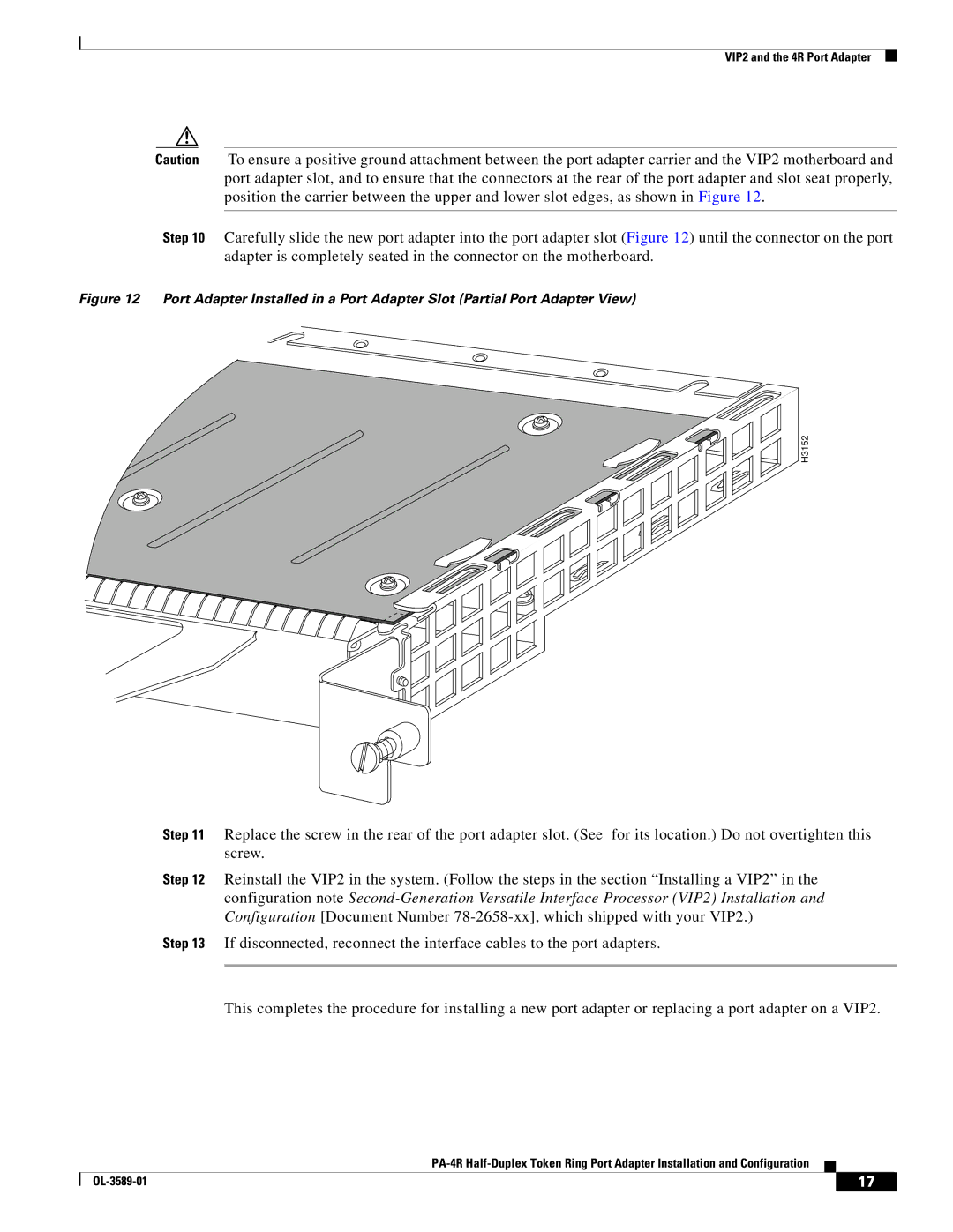
Caution To ensure a positive ground attachment between the port adapter carrier and the VIP2 motherboard and port adapter slot, and to ensure that the connectors at the rear of the port adapter and slot seat properly, position the carrier between the upper and lower slot edges, as shown in Figure 12.
Step 10 Carefully slide the new port adapter into the port adapter slot (Figure 12) until the connector on the port adapter is completely seated in the connector on the motherboard.
Figure 12 Port Adapter Installed in a Port Adapter Slot (Partial Port Adapter View)
H3152
Step 11 Replace the screw in the rear of the port adapter slot. (See for its location.) Do not overtighten this screw.
Step 12 Reinstall the VIP2 in the system. (Follow the steps in the section “Installing a VIP2” in the configuration note
Step 13 If disconnected, reconnect the interface cables to the port adapters.
This completes the procedure for installing a new port adapter or replacing a port adapter on a VIP2.
| 17 |
| |
|
|