VIP Port Adapter Functions
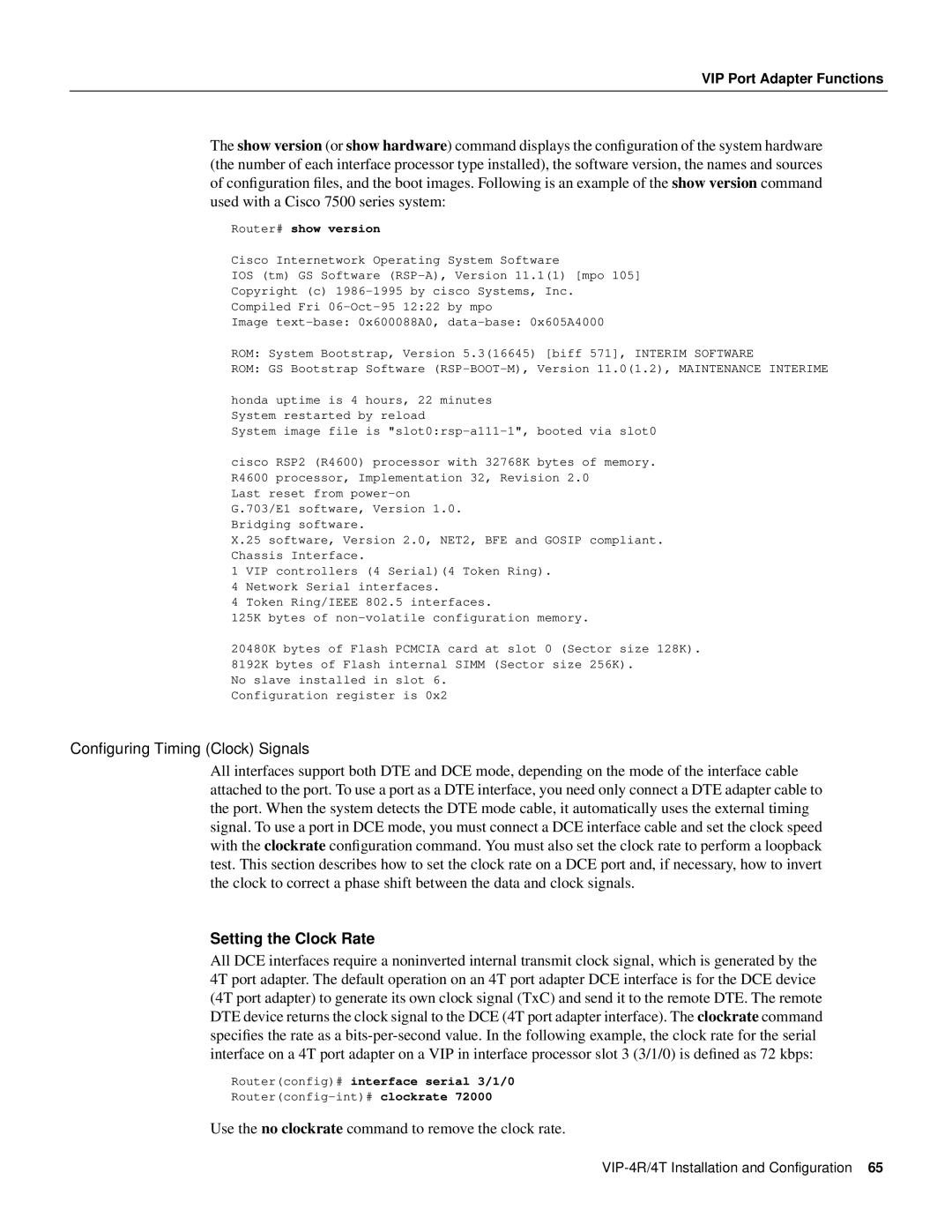
The show version (or show hardware) command displays the configuration of the system hardware (the number of each interface processor type installed), the software version, the names and sources of configuration files, and the boot images. Following is an example of the show version command used with a Cisco 7500 series system:
Router# show version
Cisco Internetwork Operating System Software
IOS (tm) GS Software
Copyright (c)
Compiled Fri
Image
ROM: System Bootstrap, Version 5.3(16645) [biff 571], INTERIM SOFTWARE
ROM: GS Bootstrap Software
honda uptime is 4 hours, 22 minutes System restarted by reload
System image file is "slot0:rsp-a111-1", booted via slot0
cisco RSP2 (R4600) processor with 32768K bytes of memory. R4600 processor, Implementation 32, Revision 2.0
Last reset from
X.25 software, Version 2.0, NET2, BFE and GOSIP compliant. Chassis Interface.
1 VIP controllers (4 Serial)(4 Token Ring).
4 Network Serial interfaces.
4 Token Ring/IEEE 802.5 interfaces.
125K bytes of
20480K bytes of Flash PCMCIA card at slot 0 (Sector size 128K). 8192K bytes of Flash internal SIMM (Sector size 256K).
No slave installed in slot 6. Configuration register is 0x2
Configuring Timing (Clock) Signals
All interfaces support both DTE and DCE mode, depending on the mode of the interface cable attached to the port. To use a port as a DTE interface, you need only connect a DTE adapter cable to the port. When the system detects the DTE mode cable, it automatically uses the external timing signal. To use a port in DCE mode, you must connect a DCE interface cable and set the clock speed with the clockrate configuration command. You must also set the clock rate to perform a loopback test. This section describes how to set the clock rate on a DCE port and, if necessary, how to invert the clock to correct a phase shift between the data and clock signals.
Setting the Clock Rate
All DCE interfaces require a noninverted internal transmit clock signal, which is generated by the 4T port adapter. The default operation on an 4T port adapter DCE interface is for the DCE device (4T port adapter) to generate its own clock signal (TxC) and send it to the remote DTE. The remote DTE device returns the clock signal to the DCE (4T port adapter interface). The clockrate command specifies the rate as a
Router(config)# interface serial 3/1/0
Use the no clockrate command to remove the clock rate.
