Versatile Interface Processor Functions
Following is the procedure for replacing or upgrading DRAM SIMMs.
Step 1 Attach an
Step 2 Disconnect all cables from the VIP and remove it from the chassis using the procedure in the section “Removing a VIP” on page 16.
Step 3 Place the VIP on a flat surface (preferably an antistatic mat or foam), and turn it so the face plate is away from you and the connector edge is toward you. (approximately opposite of the orientation shown in Figure 11).
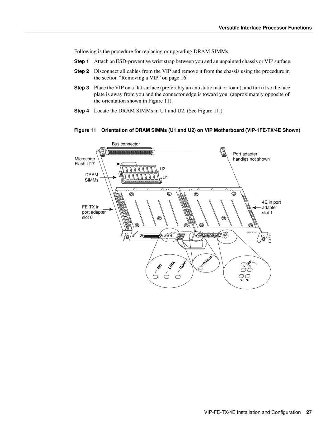
Step 4 Locate the DRAM SIMMs in U1 and U2. (See Figure 11.)
Figure 11 Orientation of DRAM SIMMs (U1 and U2) on VIP Motherboard (VIP-1FE-TX/4E Shown)
| Bus connector | |
Microcode | Port adapter | |
handles not shown | ||
Flash U17 | U2 | |
| ||
DRAM | U1 | |
SIMMs | ||
| ||
4E in port | ||
adapter | ||
port adapter | slot 1 | |
slot 0 |
|
FAST ETHERNET
0
MII | LINK | RJ45 |
0 | 1 | 2 | 3 |
1 | LINK |
3 | |
0 | 2 |
H4711