VIP Port Adapter Functions
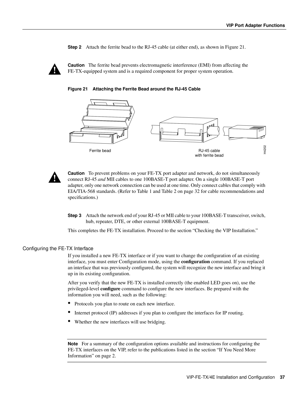
Step 2 Attach the ferrite bead to the RJ-45 cable (at either end), as shown in Figure 21.
Caution The ferrite bead prevents electromagnetic interference (EMI) from affecting the FE-TX-equipped system and is a required component for proper system operation.
Figure 21 Attaching the Ferrite Bead around the RJ-45 Cable
Ferrite bead | RJ-45 cable |
| with ferrite bead |
Caution To prevent problems on your FE-TX port adapter and network, do not simultaneously connect RJ-45 and MII cables to one 100BASE-T port adapter. On a single 100BASE-T port adapter, only one network connection can be used at one time. Only connect cables that comply with EIA/TIA-568 standards. (Refer to Table 1 and Table 2 on page 32 for cable recommendations and specifications.)
Step 3 Attach the network end of your RJ-45 or MII cable to your 100BASE-T transceiver, switch, hub, repeater, DTE, or other external 100BASE-T equipment.
This completes the FE-TX installation. Proceed to the section “Checking the VIP Installation.”
Configuring the FE-TX Interface
If you installed a new FE-TX interface or if you want to change the configuration of an existing interface, you must enter Configuration mode, using the configuration command. If you replaced an interface that was previously configured, the system will recognize the new interface and bring it up in its existing configuration.
After you verify that the new FE-TX is installed correctly (the enabled LED goes on), use the privileged-level configure command to configure the new interfaces. Be prepared with the information you will need, such as the following:
Protocols you plan to route on each new interface.
Internet protocol (IP) addresses if you plan to configure the interfaces for IP routing.
Whether the new interfaces will use bridging.
Note For a summary of the configuration options available and instructions for configuring the FE-TX interfaces on the VIP, refer to the publications listed in the section “If You Need More Information” on page 2.
VIP-FE-TX/4E Installation and Configuration 37