Cisco Systems VIP-FE-TX/4E manual Receive Data + RxD+, Transmit Data + TxD+

Models: VIP-FE-TX/4E

1 58
Download 58 pages 23.85 Kb
Page 34
Image 34
Receive Data + (RxD+)

VIP Port Adapter Functions

Table 3 FE-TX RJ-45 Connector Pinout

Pin

Description

1

Receive Data + (RxD+)


2

RxD–


3

Transmit Data + (TxD+)


6

TxD–


Note Referring to the RJ-45 pinout in Table 3, proper common-mode line terminations should be used for the unused Category 5, UTP cable pairs 4/5 and 7/8. Common-mode termination reduces the contributions to electromagnetic interference (EMI) and susceptibility to common-mode sources. Wire pairs 4/5 and 7/8 are actively terminated in the RJ-45, 100BASE-TX port circuitry in the FE-TX port adapter.

Depending on your RJ-45 interface cabling requirements, use the pinouts in Figure 17 and Figure 18.

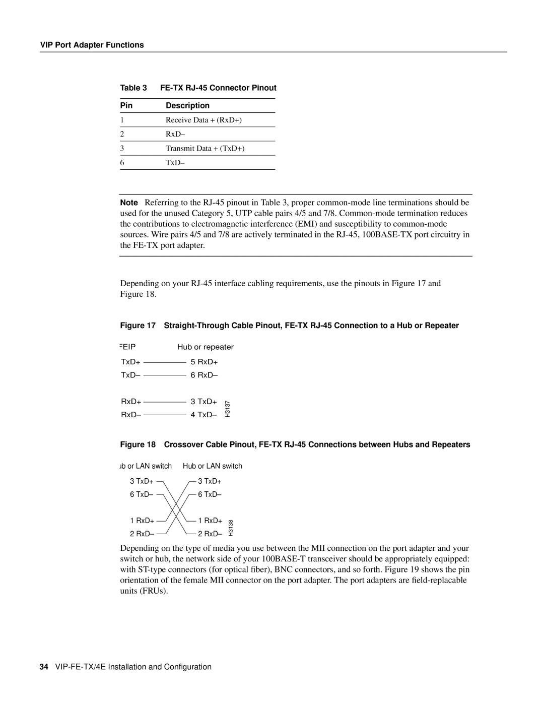
Figure 17 Straight-Through Cable Pinout, FE-TX RJ-45 Connection to a Hub or Repeater

FEIP

TxD+

TxD–

RxD+

RxD–

Hub or repeater

5RxD+

6RxD–

3 TxD+

H3137

4 TxD–

Figure 18 Crossover Cable Pinout, FE-TX RJ-45 Connections between Hubs and Repeaters

ub or LAN switch

3TxD+

6TxD–

1RxD+

2RxD–

Hub or LAN switch

3TxD+

6TxD–

1 RxD+

H3138

2 RxD–

Depending on the type of media you use between the MII connection on the port adapter and your switch or hub, the network side of your 100BASE-T transceiver should be appropriately equipped: with ST-type connectors (for optical fiber), BNC connectors, and so forth. Figure 19 shows the pin orientation of the female MII connector on the port adapter. The port adapters are field-replacable units (FRUs).

34VIP-FE-TX/4E Installation and Configuration

Page 34
Image 34
Cisco Systems manual Receive Data + RxD+, Transmit Data + TxD+, VIP-FE-TX/4E Installation and Configuration