Cisco Systems VIP-FE-TX/4E manual The bus recognizes the FE-TX-equipped VIP

Models: VIP-FE-TX/4E

1 58
Download 58 pages 23.85 Kb
Page 32
Image 32
•The bus recognizes the FE-TX-equipped VIP.

VIP Port Adapter Functions

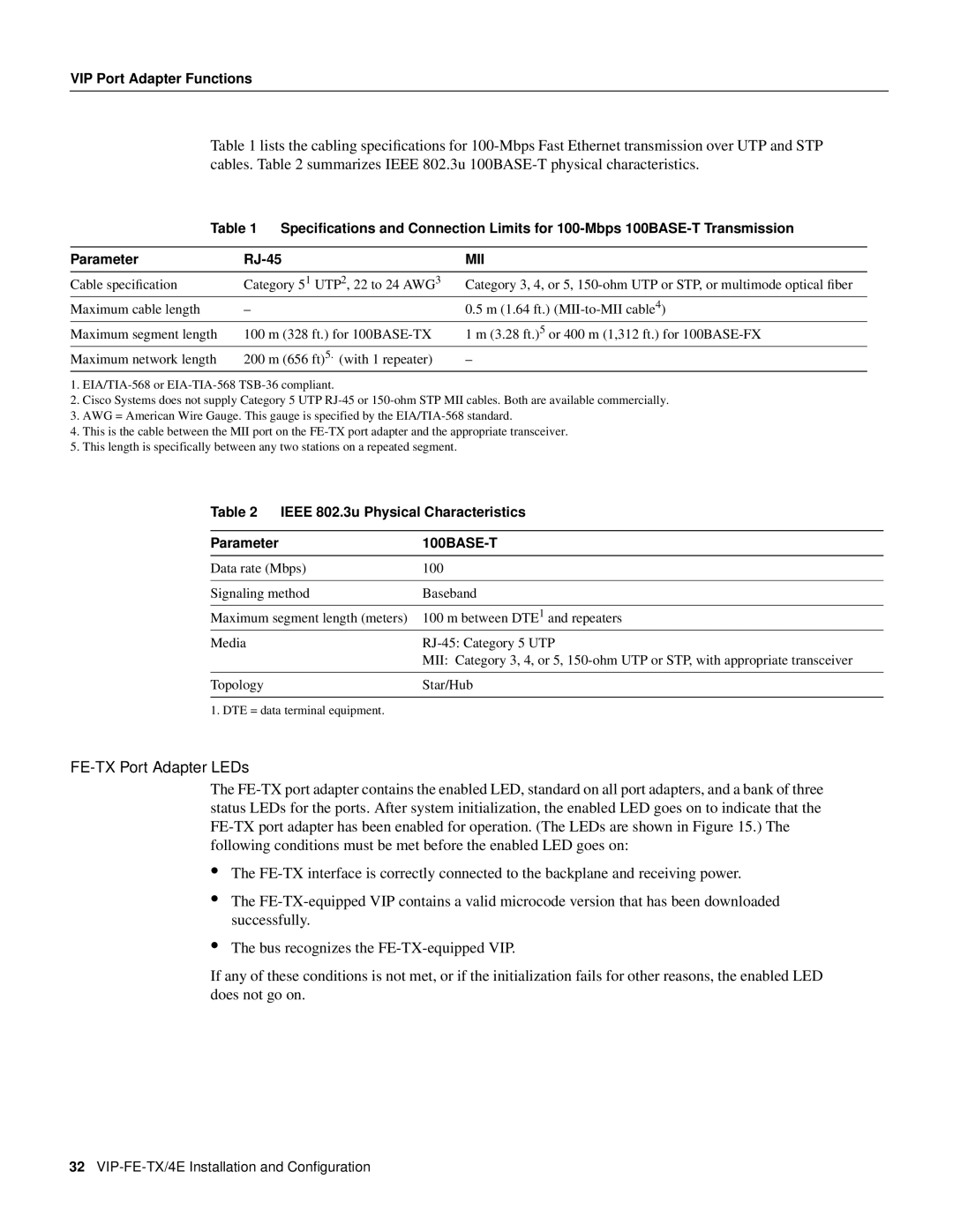
Table 1 lists the cabling specifications for 100-Mbps Fast Ethernet transmission over UTP and STP cables. Table 2 summarizes IEEE 802.3u 100BASE-T physical characteristics.

Table 1

Specifications and Connection Limits for 100-Mbps 100BASE-T Transmission


Parameter

RJ-45

MII


Cable specification

Category 5 1 UTP2, 22 to 24 AWG3

Category 3, 4, or 5, 150-ohm UTP or STP, or multimode optical fiber

Maximum cable length


4


0.5 m (1.64 ft.) (MII-to-MII cable)

Maximum segment length

100 m (328 ft.) for 100BASE-TX

1 m (3.28 ft.)5 or 400 m (1,312 ft.) for 100BASE-FX

Maximum network length

200 m (656 ft)5. (with 1 repeater)

1.EIA/TIA-568 or EIA-TIA-568 TSB-36 compliant.

2.Cisco Systems does not supply Category 5 UTP RJ-45 or 150-ohm STP MII cables. Both are available commercially.

3.AWG = American Wire Gauge. This gauge is specified by the EIA/TIA-568 standard.

4.This is the cable between the MII port on the FE-TX port adapter and the appropriate transceiver.

5.This length is specifically between any two stations on a repeated segment.

Table 2 IEEE 802.3u Physical Characteristics

Parameter

100BASE-T

Data rate (Mbps)

100


Signaling method

Baseband


Maximum segment length (meters)

100 m between DTE1 and repeaters

Media

RJ-45: Category 5 UTP


MII: Category 3, 4, or 5, 150-ohm UTP or STP, with appropriate transceiver


Topology

Star/Hub


1. DTE = data terminal equipment.

FE-TX Port Adapter LEDs

The FE-TX port adapter contains the enabled LED, standard on all port adapters, and a bank of three status LEDs for the ports. After system initialization, the enabled LED goes on to indicate that the FE-TX port adapter has been enabled for operation. (The LEDs are shown in Figure 15.) The following conditions must be met before the enabled LED goes on:

The FE-TX interface is correctly connected to the backplane and receiving power.

The FE-TX-equipped VIP contains a valid microcode version that has been downloaded successfully.

The bus recognizes the FE-TX-equipped VIP.

If any of these conditions is not met, or if the initialization fails for other reasons, the enabled LED does not go on.

32VIP-FE-TX/4E Installation and Configuration

Page 32
Image 32
Cisco Systems VIP-FE-TX/4E manual The bus recognizes the FE-TX-equipped VIP