Versatile Interface Processor Functions
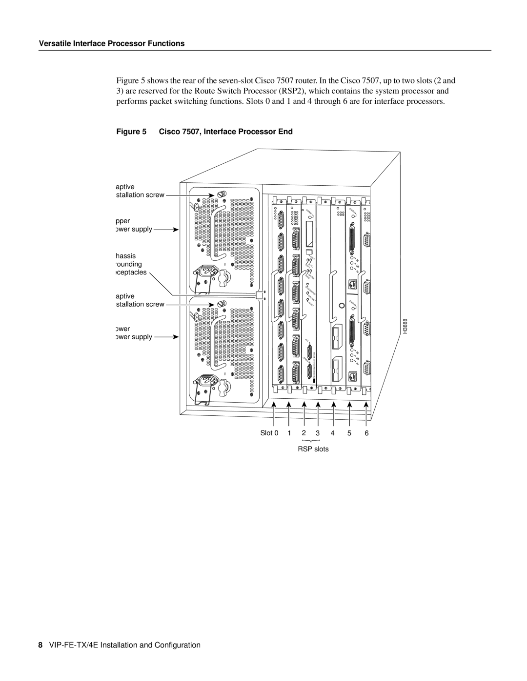
Figure 5 shows the rear of the seven-slot Cisco 7507 router. In the Cisco 7507, up to two slots (2 and
3)are reserved for the Route Switch Processor (RSP2), which contains the system processor and performs packet switching functions. Slots 0 and 1 and 4 through 6 are for interface processors.
Figure 5 Cisco 7507, Interface Processor End
aptive stallation screw
| DC |
| FAIL |
| AC |
| POWER |
pper |
|
ower supply |
|
hassis |
|
rounding | I |
eceptacles |
|
| O |
aptive |
|
stallation screw |
|
| DC |
| FAIL |
| AC |
| POWER |
ower |
|
ower supply |
|
| I |
| O |
|
| NORMAL |
|
| ENABLE |
| |
|
|
|
|
|
| ||
|
|
| EJECT |
|
|
| |
|
| SLOT | SLOT | 1 |
|
|
|
|
| 0 |
|
|
| ||
|
| SLAVEMASTER |
|
|
| ||
|
| SLAVE/MASTER |
|
|
| ||
|
|
| CPU | HALT |
|
|
|
|
|
|
|
| ENABLE |
| |
|
|
| RESET |
|
| ||
|
|
|
|
|
|
| H3888 |
|
| AUX. |
|
|
|
| |
|
| CONSOLE | ROUTE |
|
|
| |
|
| SWITCHPROCESSOR2 |
|
|
| ||
|
|
|
|
|
|
| |
Slot 0 | 1 | 2 |
| 3 | 4 | 5 | 6 |
RSP slots
8