iDP3310 User's Manual
8. DRAWER KICK-OUT CONNECTOR AND POWER CONNECTOR
8.1Specifications of Drawer Kick-Out Connector(Option)
(1)Drawer
The pulses specified by the BELL command(07h) are output.(Approx. 200 ms)
(2)Electrical characteristics
1)Drive voltage: 12V DC +/− 1V
2)Drive current: 0.8 A at maximum
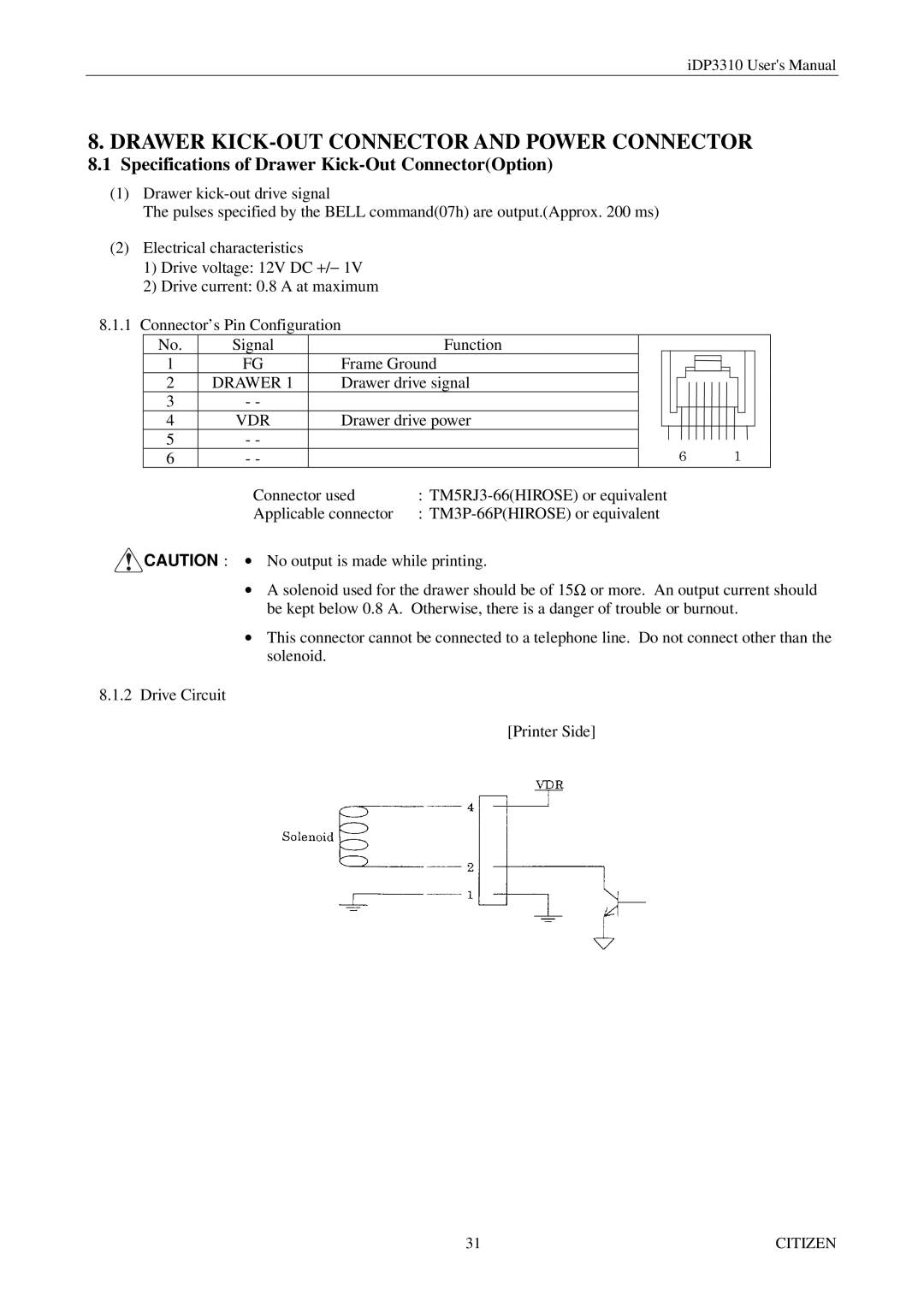
8.1.1 Connector’s Pin Configuration
No. | Signal |
| Function |
|
|
|
|
|
|
|
|
|
|
|
|
|
1 | FG | Frame Ground |
|
|
|
|
|
|
|
|
|
|
|
|
| |
2 | DRAWER 1 | Drawer drive signal |
|
|
|
|
|
|
|
|
|
|
|
|
| |
3 | - - |
|
|
|
|
|
|
|
|
|
|
|
|
|
|
|
4 | VDR | Drawer drive power |
|
|
|
|
|
|
|
|
|
|
|
|
| |
|
|
|
|
|
|
|
|
|
|
|
|
| ||||
|
|
|
|
|
|
|
|
|
|
|
|
|
|
|
|
|
5 | - - |
|
|
|
|
|
|
|
|
|
|
|
|
|
|
|
6 | - - |
|
|
|
|
|
|
|
|
|
|
|
|
|
|
|
| Connector used | : | ||||||||||||||
| Applicable connector | : | ||||||||||||||
![]() CAUTION : ∙ No output is made while printing.
CAUTION : ∙ No output is made while printing.
∙A solenoid used for the drawer should be of 15Ω or more. An output current should be kept below 0.8 A. Otherwise, there is a danger of trouble or burnout.
∙This connector cannot be connected to a telephone line. Do not connect other than the solenoid.
8.1.2 Drive Circuit
[Printer Side]
31 | CITIZEN |
