VRX610 specifications
The Clarion VRX610 is a versatile and feature-rich multimedia receiver designed for the modern driver seeking both entertainment and functionality on the road. With its sleek, user-friendly design and robust technological capabilities, the VRX610 stands out as an excellent choice for those looking to enhance their in-car experience.One of the main attractions of the Clarion VRX610 is its 6.2-inch touchscreen display, which offers a vibrant and clear interface for easy navigation through menus and settings. The responsive touchscreen allows users to access various features with a simple tap, making it convenient to switch between sources and adjust settings while driving.
The VRX610 supports multiple media formats, including CDs, DVDs, and USB drives, providing ample options for enjoying music and videos during your journey. With built-in Bluetooth technology, users can easily connect their smartphones for hands-free calling and audio streaming. This feature not only enhances safety but also allows for seamless access to music libraries and streaming services.
This multimedia receiver is equipped with a built-in AM/FM tuner and supports HD Radio, ensuring access to high-quality radio stations. For those who prefer satellite radio, the VRX610 is compatible with SiriusXM, providing an even wider range of listening options.
For audiophiles, the Clarion VRX610 offers adjustable audio settings, including a 3-band graphic equalizer, allowing users to customize sound profiles to their liking. The built-in amplifier delivers powerful, clear sound, while the unit also supports external amplification for those looking to create a more advanced audio setup.
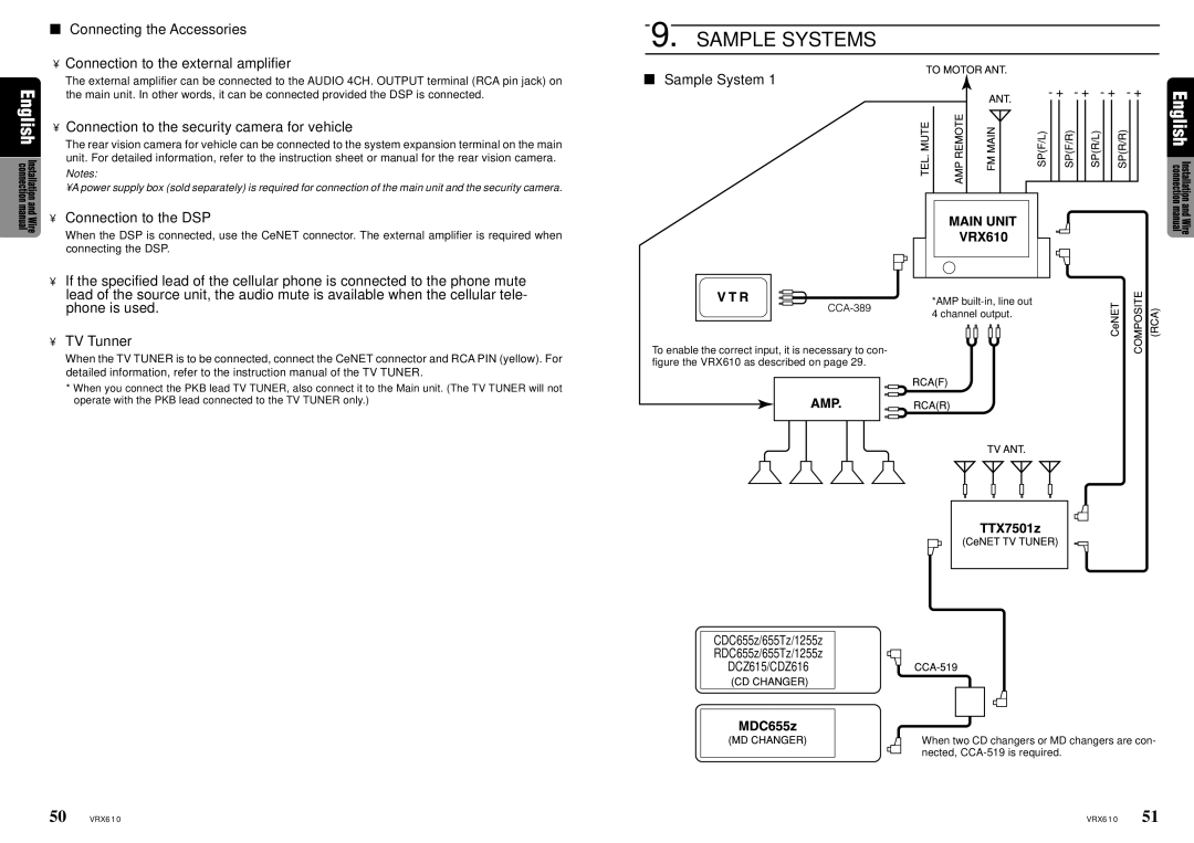
In terms of connectivity, the VRX610 features multiple inputs and outputs, including a dedicated rear camera input for enhanced safety when reversing, as well as support for additional screens or video outputs. The device is compatible with both Apple CarPlay and Android Auto, enabling users to easily access navigation, messaging, and music apps directly from the receiver’s display.
Overall, the Clarion VRX610 combines cutting-edge technology with intuitive features, making it a compelling choice for anyone looking to upgrade their vehicle's multimedia system. Its robust capabilities, user-centric design, and superior sound quality ensure that every drive can be an enjoyable experience, whether it’s a short trip or a long journey.

