chapter 4
REMOVAL AND REPLACEMENT PROCEDURES
This chapter provides general service information for the computer. Adherence to the procedures and precautions described in this chapter is essential for proper service.
After completing all necessary removal and replacement procedures, run the Diagnostics utility to verify that all components operate properly.
4.1Disassembly Sequence Chart
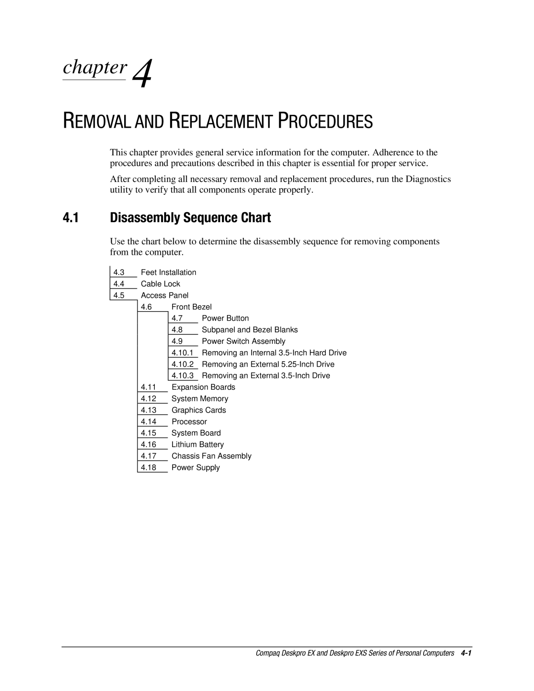
Use the chart below to determine the disassembly sequence for removing components from the computer.
4.3Feet Installation
4.4Cable Lock
4.5Access Panel
4.6Front Bezel
4.7Power Button
4.8Subpanel and Bezel Blanks
4.9Power Switch Assembly
4.10.1Removing an Internal
4.10.2Removing an External
4.10.3Removing an External
4.11Expansion Boards
4.12System Memory
4.13Graphics Cards
4.14Processor
4.15System Board
4.16Lithium Battery
4.17Chassis Fan Assembly
4.18Power Supply
Compaq Deskpro EX and Deskpro EXS Series of Personal Computers