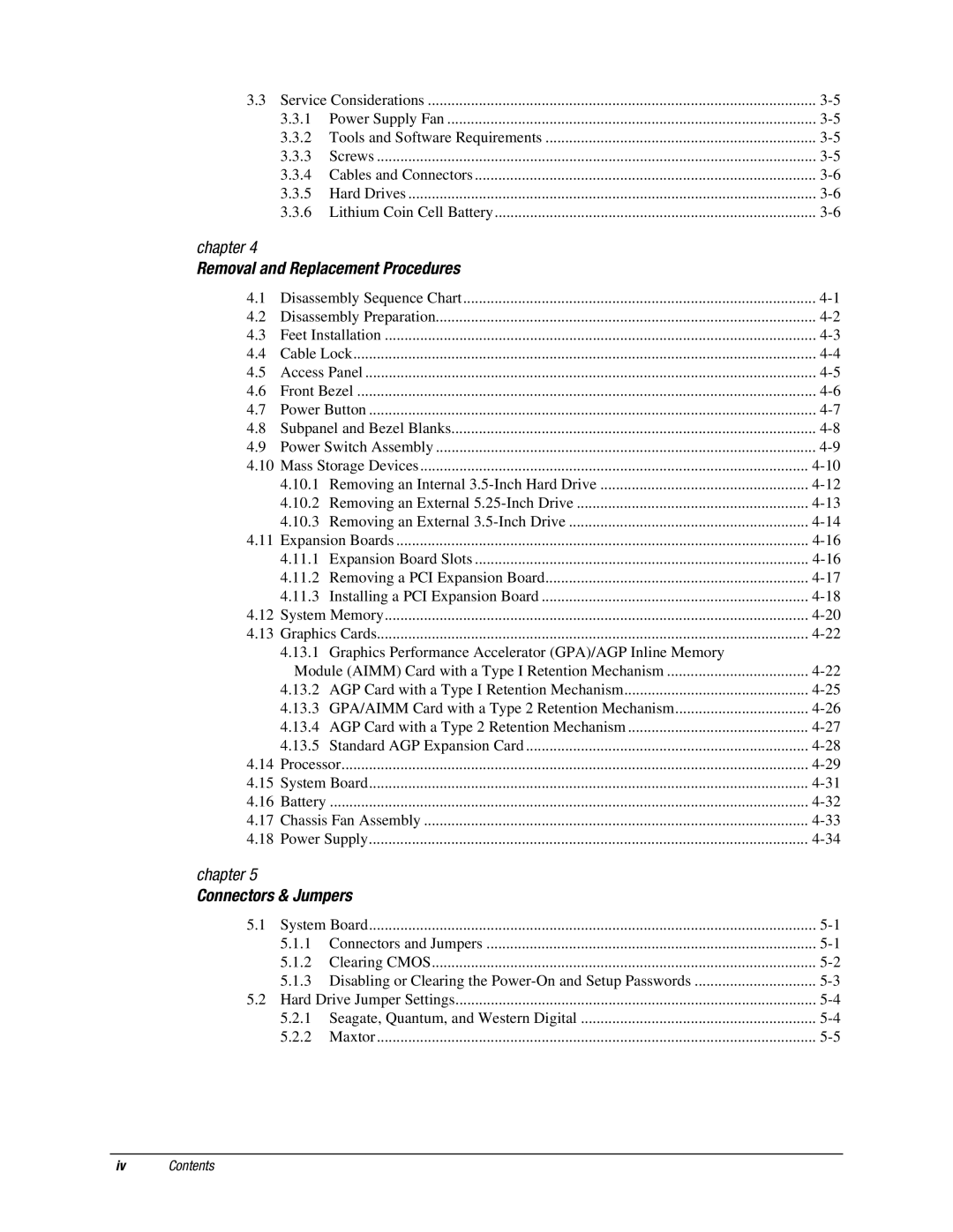
3.3 Service Considerations | ||
3.3.1 | Power Supply Fan | |
3.3.2 Tools and Software Requirements | ||
3.3.3 | Screws | |
3.3.4 | Cables and Connectors | |
3.3.5 | Hard Drives | |
3.3.6 Lithium Coin Cell Battery | ||
chapter 4
Removal and Replacement Procedures
4.1 | Disassembly Sequence Chart | |
4.2 | Disassembly Preparation | |
4.3 | Feet Installation | |
4.4 | Cable Lock | |
4.5 | Access Panel | |
4.6 | Front Bezel | |
4.7 | Power Button | |
4.8 | Subpanel and Bezel Blanks | |
4.9 | Power Switch Assembly | |
4.10 | Mass Storage Devices | |
| 4.10.1 Removing an Internal | |
| 4.10.2 Removing an External | |
| 4.10.3 Removing an External | |
4.11 | Expansion Boards | |
| 4.11.1 Expansion Board Slots | |
| 4.11.2 Removing a PCI Expansion Board | |
| 4.11.3 Installing a PCI Expansion Board | |
4.12 | System Memory | |
4.13 | Graphics Cards | |
| 4.13.1 Graphics Performance Accelerator (GPA)/AGP Inline Memory |
|
| Module (AIMM) Card with a Type I Retention Mechanism | |
| 4.13.2 AGP Card with a Type I Retention Mechanism | |
| 4.13.3 GPA/AIMM Card with a Type 2 Retention Mechanism | |
| 4.13.4 AGP Card with a Type 2 Retention Mechanism | |
| 4.13.5 Standard AGP Expansion Card | |
4.14 | Processor | |
4.15 | System Board | |
4.16 | Battery | |
4.17 | Chassis Fan Assembly | |
4.18 | Power Supply |
chapter 5
Connectors & Jumpers
5.1 | System Board | ||
| 5.1.1 | Connectors and Jumpers | |
| 5.1.2 | Clearing CMOS | |
| 5.1.3 Disabling or Clearing the | ||
5.2 | Hard Drive Jumper Settings | ||
| 5.2.1 Seagate, Quantum, and Western Digital | ||
| 5.2.2 | Maxtor | |
ivContents
