Maintenance and Service Guide
Page
Contents
Removal and Replacement Procedures
Removal and Replacement Preliminaries
Illustrated Parts Catalog
Screw Listing Index
Product Description
Key
Models
Key Description Options
SKU#
Compaq Evo Notebook N620c Models
No configuration code used
DE271A UUF
DE270A UUF
DE265A UUF
DE264A UUF
DE263A UUF
DE262A UUF
Compaq Evo Notebook N610c Models
470050-929
470050-984
GEM/NAFTA
470050-560
470050-478
470037-546
470044-425
470037-700
470050-787
470037-605
DG348P ABG
Compaq Evo Notebook N610v Models
N6v 200 Taiwan DG350P AB0 DG349P AB0
Compaq Evo Notebook N600c Models
N600 120 Belgium 470023-411
470053-666
470053-665
N600 100 Belgium 470029-930
Features
Product Description
Power Management
Clearing a Password
Component Function
Front and Right Side Panel Components
Built-in microphone
Right Side and Rear Panel Components
Right Side and Rear Panel Components
Right Side and Rear Panel Components- Evo Notebook N600c
Right Side and Rear Panel Components
Bottom Components
Bottom Components-Evo Notebook N620c, N610c, and N610v
Bottom Components
Bottom Components-Evo Notebook N600c
Bottom Components
Top Components
Top Components
Top Components
Item Component Function
Keyboard Components
Design Overview
Computer Setup Diagnostics Utilities
Troubleshooting
Using Computer Setup
Select To Do This
File Menu
Security Menu
Selecting from the Security Menu
Advanced Menu
Selecting from the Advanced Menu
Advanced Menu
Obtaining, Saving, or Printing Configuration Information
Using Compaq Diagnostics
Obtaining, Saving, or Printing Diagnostic Test Information
Maintenance and Service Guide
Troubleshooting Flowcharts Overview
Troubleshooting Flowcharts
Flowchart Description
Power?
Flowchart 2.1 Initial Troubleshooting
Done
Flowchart 2.2 No Power, Part
Flowchart 2.3 No Power, Part
Plug directly Into AC outlet Power LED On? Done
Flowchart 2.4 No Power, Part
Flowchart 2.5 No Power, Part
Flowchart 2.6 No Video, Part
From Flowchart No Video, Part Remove
Flowchart 2.7 No Video, Part
Switch box
Flowchart 2.8 Nonfunctioning Docking Station if applicable
Flowchart 2.9 No Operating System OS Loading
Flowchart 2.10 No OS Loading from Hard Drive, Part
Board
Flowchart 2.11 No OS Loading from Hard Drive, Part
Clean virus
Flowchart 2.12 No OS Loading from Hard Drive, Part
Flowchart 2.13 No OS Loading from Diskette Drive
Flowchart 2.14 No OS Loading from CD- or DVD-ROM Drive
Go to Flowchart No Audio, Part Undock
Flowchart 2.15 No Audio, Part
Flowchart 2.16 No Audio, Part
Cmos
Flowchart 2.17 Nonfunctioning Device
Flowchart 2.18 Nonfunctioning Keyboard
Flowchart 2.19 Nonfunctioning Pointing Device
Flowchart 2.20 No Network or Modem Connection
Serial Number Location
Illustrated Parts Catalog
Illustrated Parts Catalog
Spare Parts Notebook System Major Components
Switch cover
Spare Part
Description Number Displays
Illustrated Parts Catalog
Spare Part
Illustrated Parts Catalog
TouchPad components
Description Number Miscellaneous Plastics Kit
Illustrated Parts Catalog
Top covers
Item Description Number Memory expansion boards
Fans
Illustrated Parts Catalog
Heat sink
Item Description Number System boards
DC-DC converter boards
Processors
Illustrated Parts Catalog
Hard drives
Item Description Number Base enclosures
Mini PCI communications boards
Illustrated Parts Catalog
Description Number Media Bay devices
Miscellaneous Plastics Kit Components
Miscellaneous Plastics Kit Components
Item Description
Miscellaneous Plastics Kit Components Spare Part Number
Mass Storage Devices
Mass Storage Devices
Mass Storage Devices
Mass Storage Devices
Iomega 250-MB Zip drive
Description Number Optical drives
2X Max SuperDisk LS120 drive
Spare Parts Miscellaneous not illustrated
Miscellaneous
RJ-11 P55 adapters
Description Number Power cord, black, 6 feet
RJ-45 network cable
Tools Required
Removal and Replacement Preliminaries
Plastic Parts
Service Considerations
Preventing Damage to Removable Drives
Preventing Electrostatic Damage
Packaging and Transporting Precautions
Workstation Precautions
Grounding Equipment and Methods
Static-Shielding Materials
Typical Electrostatic Voltage Levels
Relative Humidity Event 10% 40% 55%
Material Use Voltage Protection Level
Removal and Replacement Procedures
Disassembly Sequence Chart
Disassembly Sequence Chart
Serial Number
Section Description Removed
Disassembly Sequence Chart
Battery Pack, 6-cell, Li ion Spare Part Number Information
Preparing the Notebook for Disassembly
Reverse the preceding procedure to install the battery pack
Media Bay Devices Spare Part Number Information
Removing a Media Bay Device
Hard Drive Spare Part Number Information
Reverse the preceding procedure to install the hard drive
Removing the Hard Drive Bezel
Replacing the Notebook Feet
Mini PCI Communications Board Spare Part Number Information
Mini PCI Communications Board
Removing the Mini PCI Compartment Cover
Removing the Mini PCI Communications Board
Disk Cell RTC Battery
Removing the Disk Cell RTC Battery
Keyboard Spare Part Number Information
Keyboard
Keyboard with Pointstick
Keyboard Spare Part Number Information
10. Removing the Keyboard Screw
11. Releasing the Keyboard
12. Disconnecting the Pointing Device and Keyboard Cables
Memory Expansion Board Spare Part Number Information
Memory Expansion
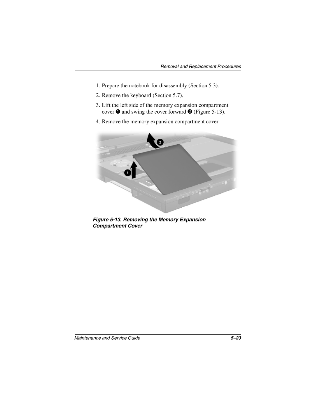
13. Removing the Memory Expansion Compartment Cover
14. Removing a Memory Expansion Board
TouchPad Components Spare Part Number Information
TouchPad
15. Removing the TouchPad
Switch Cover Spare Part Number Information
Switch Cover
Switch cover 241438-001
17. Removing the Switch Cover
Display Spare Part Number Information
Display
18. Disconnecting the Display Cables
Reverse the preceding procedure to replace the display
Top Cover Spare Part Number Information
Top Cover
20. Removing the Top Cover Screws
For Evo Notebook N620c, N610c, N610v models
System Board Spare Part Number Information
System Board
Removal and Replacement Procedures
Maintenance and Service Guide
24. Do Not Remove These Screws
25. Removing the System Board
Removal and Replacement Procedures
Reverse the preceding procedure to replace the system board
Fan Spare Part Number Information
14 Fan
Disconnect the fan cable from the system board Figure
29. Removing the Fan on an Evo Notebook N600c
Maintenance and Service Guide
Heat Sink Spare Part Number Information
Heat Sink
Heat sink 303103-001
31. Disconnecting the Fan Cable
32. Removing the Heat Sink Screws
Reverse the preceding procedure to replace the heat sink
Processor Spare Part Number Information
Processor
Reverse the preceding procedure to replace the processor
DC-DC Converter Board Spare Part Number Information
DC-DC Converter Board
35. Removing the DC-DC Converter Board
Modem Cable
Remove the modem cable
37. Routing the Modem Cable in the Base Enclosure
Weight
Dimensions
Stand-alone battery power requirements
AC adapter power requirements
Relative humidity noncondensing
Temperature
Shock
Vibration
Inch XGA, TFT Display
Hard Drives
Buffer size3
40.0 GB 30.0 GB 20.0 GB 15.0 GB Physical Configuration
Disk rotational
Speed Transfer rate
Diskette Drive
CD-ROM Drive
Disc thickness Track pitch
DVD-ROM Drive
Audio output level
Center hole diameter
CD-RW Drive
Disk diameter
Disk thickness
Power supply input
Cell, Li ion Battery Pack
AC Adapter
Energy
Hardware DMA System Function
System DMA
Hardware IRQ System Function
System Interrupts
System I/O Addresses
System I/O Addresses
VGA
Size Memory Address System Function
System Memory Map
Pin Signal Audio
Pin Signal Audio out
Table A-1 Stereo Speaker/Headphone
Microphone
Table A-3 Keyboard/Mouse
Pin Signal
Table A-4 RJ-11 Modem
Table A-6 Universal Serial Bus
Table A-5 RJ-45 Network Interface
Table A-7 Serial
Table A-8 External Monitor
Table A-9 Parallel
Table A-10 Docking
Docking
Table A-10
Docking
PS2 VCC
Conductor Power Cord Set
Power Cord Set Requirements
Country-Specific Requirements
Conductor Power Cord Set Requirements
Country Accredited Agency Applicable Note Number
BSI
Screw Listing
Table C-1 Phillips Metric 2.5 × 2.5 Screw
Color Qty Length Thread Width Black Where used
Head
Figure C-2. PM1.5 × 3.5 Screw Location
Table C-2 Phillips Metric 1.5 × 3.5 Screw
Figure C-3. PM2.5 × 5.0 Screw Location
Table C-3 Phillips Metric 2.5 × 5.0 Screw
Figure C-4. PM2.5 × 5.0 Screw Location
Figure C-5. TM2.5 × 7.0 Screw Locations
Table C-4 Torx T8 Metric 2.5 × 7.0 Screw
Figure C-6. TM2.5 × 7.0 Screw Locations
Figure C-7. TM2.5 × 7.0 Screw Locations
Figure C-8. TM2.5 × 5.0 Screw Locations
Table C-5 Torx T8 Metric 2.5 × 5.0 Screw
Figure C-9. TM2.5 × 5.0 Screw Locations
Table C-5 Torx T8 M2.5 × 5.0 Screw
Table C-6 Mm × 20.0 mm Bushing Guide
Color Qty Length Thread Width Silver 20 mm Where used
Figure C-11. TM2.0 × 3.0 Screw Location
Table C-7 Torx Metric 2.0 × 3.0 Screw
Figure C-12. PM2.0 × 4.0 Screw Location
Table C-8 Phillips Metric 2.0 × 4.0 Screw
Figure C-13. PM2.0 × 4.0 Screw Location
Table C-8 Phillips M2.0 × 4.0 Screw
Figure C-14. PM2.0 × 4.0 Screw Location
Index
Index-2
Index-3
Index-4
Index-5
Index-6
Index-7