CANpro/104 User Manual
Connector Pinouts
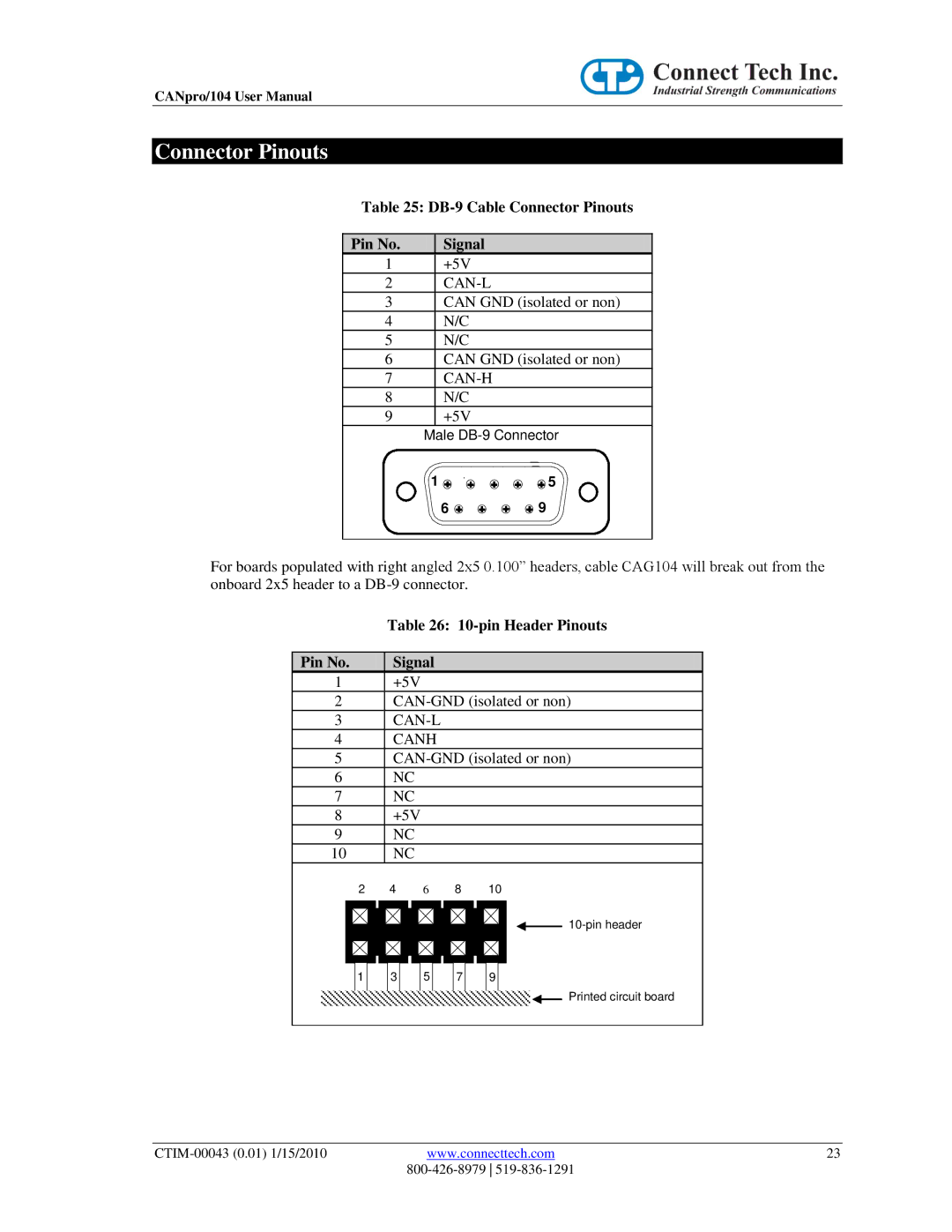
Table 25: DB-9 Cable Connector Pinouts
Pin No. |
| Signal |
1 |
| +5V |
2 |
| |
3 |
| CAN GND (isolated or non) |
4 |
| N/C |
5 |
| N/C |
6 |
| CAN GND (isolated or non) |
7 |
|
|
8 |
| N/C |
9 |
| +5V |
| Male | |
1 ![]() 6
6 ![]()
![]() 5
5 ![]() 9
9
For boards populated with right angled 2x5 0.100” headers, cable CAG104 will break out from the onboard 2x5 header to a
Table 26: 10-pin Header Pinouts
Pin No. | Signal |
1+5V
2
3
4CANH
5
6NC
7NC
8+5V
9NC
10 | NC |
2 | 4 | 6 | 8 | 10 |
1 | 3 | 5 | 7 | 9 |
Printed circuit board
www.connecttech.com | 23 | |
|
|