CANpro/104 User Manual
Interrupts and Memory I/O Range Selection
CANpro/104’s interrupt lines and I/O ranges are jumper assignable.
Interrupt Selection
J1 and J2 are used for interrupt selection. Interrupt selection for the first CAN controller is achieved via the upper and centre rows of pins on the connector. The lower and center rows of pins allow selection of interrupts for the second CAN controller. Please refer to Figure 1 to locate jumper blocks J1 and J2.
CANpro/104 offers flexible interrupt configuration. Each CANpro/104 card can use one PC/104 interrupt per controller, share one interrupt across both controllers or use no interrupts at all.
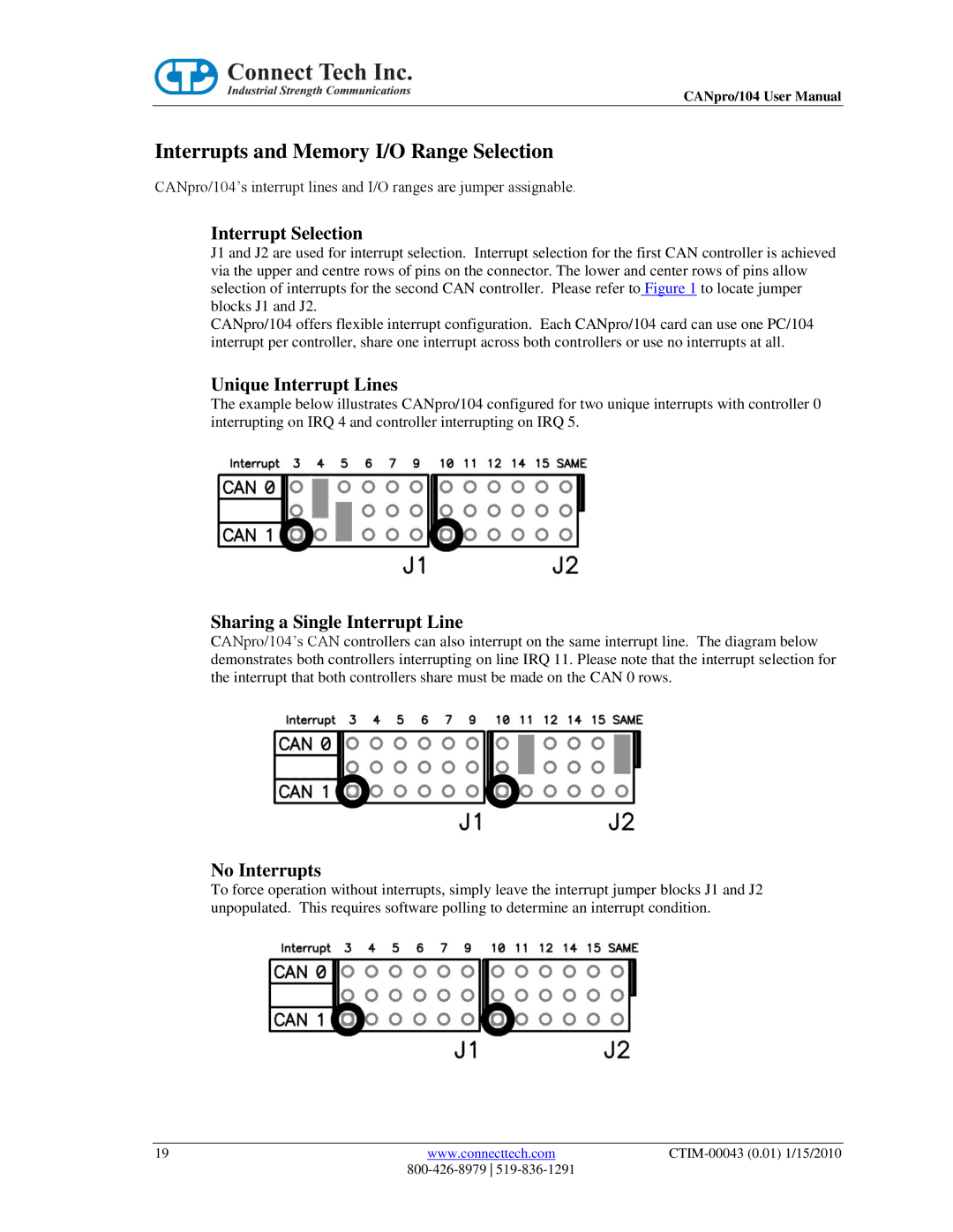
Unique Interrupt Lines
The example below illustrates CANpro/104 configured for two unique interrupts with controller 0 interrupting on IRQ 4 and controller interrupting on IRQ 5.
Sharing a Single Interrupt Line
CANpro/104’s CAN controllers can also interrupt on the same interrupt line. The diagram below demonstrates both controllers interrupting on line IRQ 11. Please note that the interrupt selection for the interrupt that both controllers share must be made on the CAN 0 rows.
No Interrupts
To force operation without interrupts, simply leave the interrupt jumper blocks J1 and J2 unpopulated. This requires software polling to determine an interrupt condition.
19 | www.connecttech.com |
|
|
|