CANpro/104 User Manual
Other On-board Jumper Selection
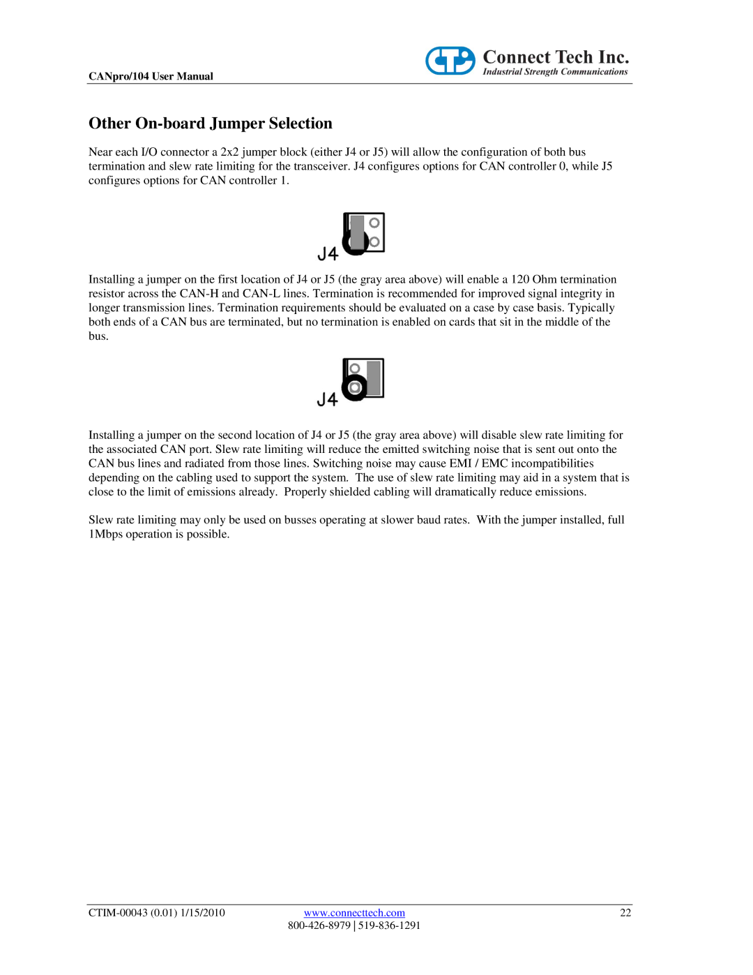
Near each I/O connector a 2x2 jumper block (either J4 or J5) will allow the configuration of both bus termination and slew rate limiting for the transceiver. J4 configures options for CAN controller 0, while J5 configures options for CAN controller 1.
Installing a jumper on the first location of J4 or J5 (the gray area above) will enable a 120 Ohm termination resistor across the
Installing a jumper on the second location of J4 or J5 (the gray area above) will disable slew rate limiting for the associated CAN port. Slew rate limiting will reduce the emitted switching noise that is sent out onto the CAN bus lines and radiated from those lines. Switching noise may cause EMI / EMC incompatibilities depending on the cabling used to support the system. The use of slew rate limiting may aid in a system that is close to the limit of emissions already. Properly shielded cabling will dramatically reduce emissions.
Slew rate limiting may only be used on busses operating at slower baud rates. With the jumper installed, full 1Mbps operation is possible.
www.connecttech.com | 22 | |
|
|