CANpro/104 User Manual
Performance Enhancement
PC/104 Memory and I/O Bus cycles are typically about 700 nS long in total, but the access speed of the SJA1000 is considerably faster. The PC/104 Bus allows Memory and I/O Bus cycles to be shortened by the assertion of the SRDY* signal at the appropriate time in the Bus Cycle. This shortening of the PC/104 Bus Cycle can yield some significant performance improvements is some applications.
The CTI CANpro/104 board allows the PC/104 Bus cycle to be shortened by about 30% with Jumper J3C Position #6.
J3C Position #6 | Function |
Removed | Normal PC/104 Bus Cycle length |
Installed | Shortened PC/104 Bus Cycle length |
Table 14
Note: Not all System boards will support Bus Cycle shortening via the PC/104 SRDY* signal. Consult with the manufacturer of your System board to determine if this feature is supported.
CAN Bus Options
The board supports 2 CAN Bus Options with Jumper J4 and J5.
J4 is associated with CAN
CAN Bus Termination
Ground the Shell of the 9D Connector
Termination
A 120 ohm termination resistor is placed across the CAN Bus signals (CANH and CANL), by placing a jumper on Position “T” of either J4 or J5. It is desirable to place a termination resistor at each physical end on a CAN Bus segment.
9D Connector Shell Ground
On CANpro/104 boards equipped with a 9D CAN Bus connector, the Metal Shell of that connector can be connected to the Isolated Ground of the board (each CAN Port has a separate Ground), by placing a jumper on Position “G” of either J4 or J5. This might be useful in some installations to reduce noise.
Interrupt Mode and Selections
The board can be operated with either one or two interrupts, the interrupt(s) can be shared with another PC/104 board (which supports shared interrupts), and the
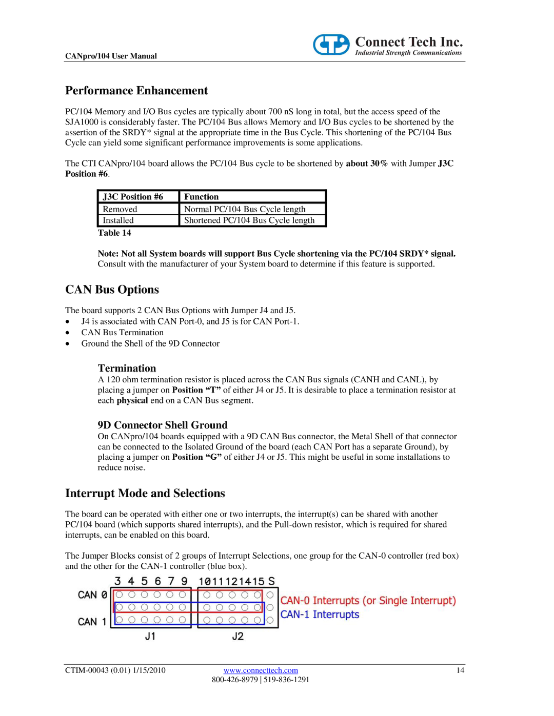
The Jumper Blocks consist of 2 groups of Interrupt Selections, one group for the
www.connecttech.com | 14 | |
|
|