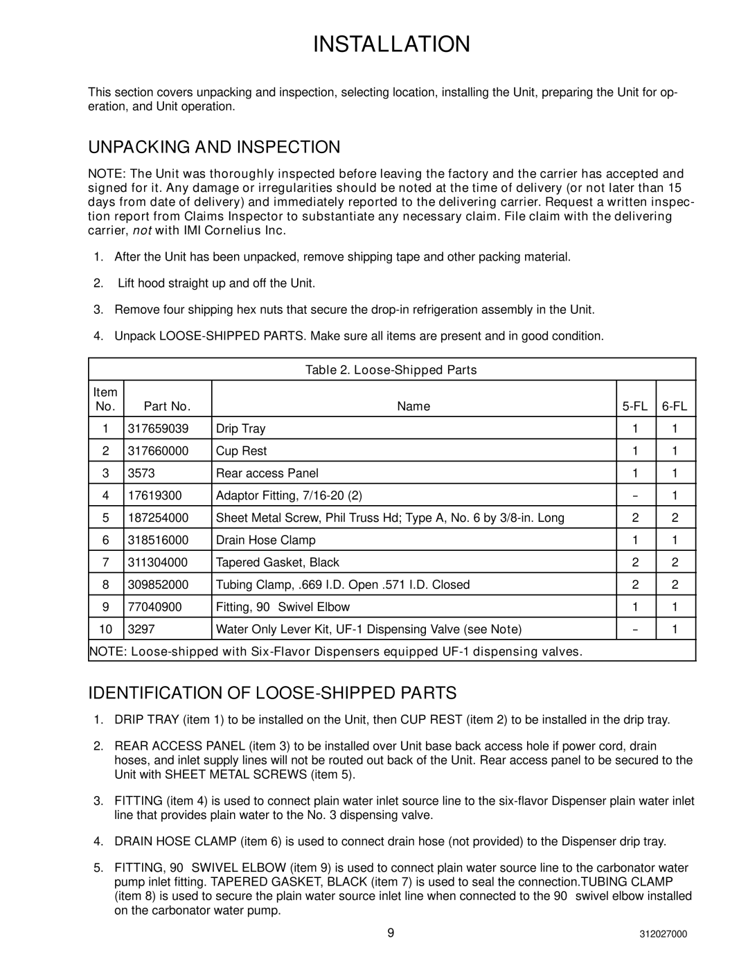
R-134A specifications
Cornelius R-134A is a refrigerant commonly used in various cooling and air conditioning applications. It belongs to the hydrofluorocarbon (HFC) family and has become a favored alternative to many ozone-depleting substances. Unlike its predecessors, R-12, which has been phased out due to its detrimental effects on the ozone layer, R-134A offers a more environmentally friendly solution, albeit still having global warming potential.One of the main features of R-134A is its favorable thermodynamic properties. It exhibits a low boiling point of approximately -26.3°C (-15.3°F), making it suitable for various refrigeration applications, including automotive air conditioning, commercial cooling systems, and domestic refrigerators. Its efficiency is regarded as superior, allowing for quick heat absorption and dissipation. This efficiency translates into energy savings, ultimately benefiting both consumers and manufacturers.
R-134A also boasts a relatively high vaporization heat, demonstrating its effectiveness in heat transfer processes. The low toxicity and non-flammability of R-134A further enhance its appeal, as it poses minimal risk during handling and application. This characteristic makes R-134A safer for technicians and users compared to older refrigerants, which presented higher health hazards.
Within modern technologies, R-134A plays a crucial role in both chiller systems and heat pump applications. It is compatible with various lubricants, allowing manufacturers to utilize R-134A in existing systems with minimal modifications. However, it is essential to use the correct type of oil, as mixing different types can lead to system inefficiencies and potential failure.
Despite its advantages, R-134A has a global warming potential of around 1,430 times greater than carbon dioxide, prompting the refrigerant industry to look for alternatives. Newer refrigerants, such as R-1234yf, offer lower environmental impact, driving a shift towards more sustainable options.
In conclusion, Cornelius R-134A remains a widely used refrigerant known for its efficiency, safety, and effectiveness in heat transfer. While it has played a significant role in the refrigeration and air conditioning industries, the ongoing search for eco-friendly alternatives highlights the need for continued innovation and adherence to environmental standards.

