Operating Controls
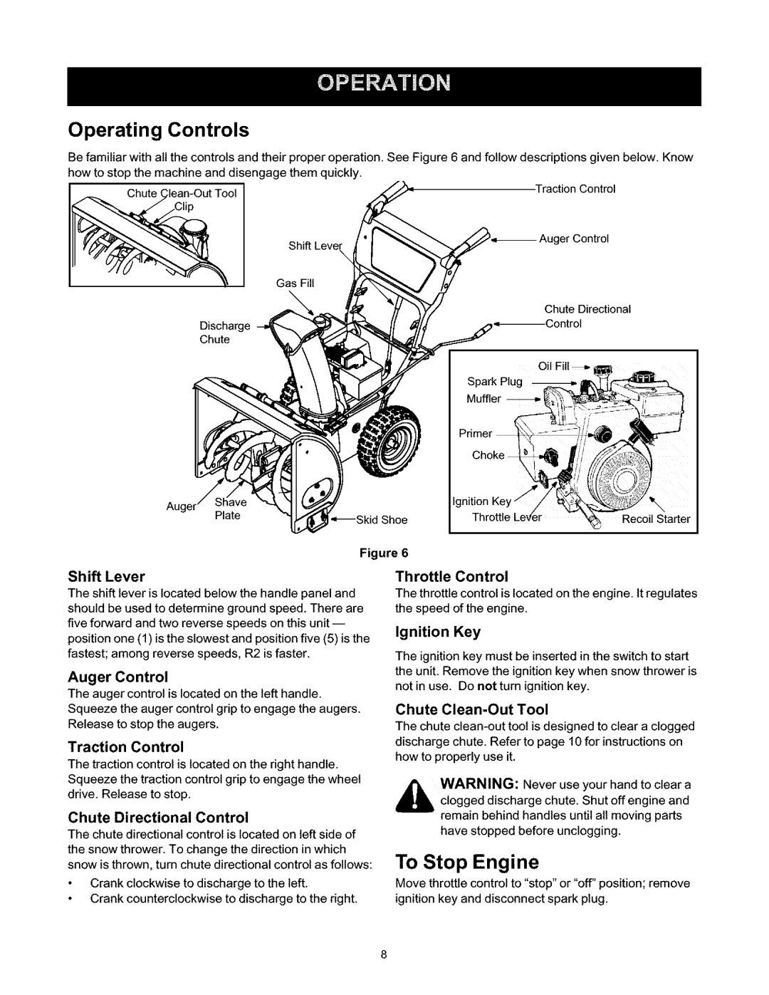
Be familiar with all the controls and their proper operation. See Figure 6 and follow descriptions given below. Know how to stop the machine and disengage them quickly.
Chute ( | Traction Control |
Shift Leve_ | ger Control |
Gas Fill
Chute Directional
Discharge | |
| |
Chute |
|
Auger
Plate | *_Skid | Shoe |
|
Figure 6
Shift Lever
The shift lever is located below the handle panel and should be used to determine ground speed. There are five forward and two reverse speeds on this
Auger Control
The auger control is located on the left handle. Squeeze the auger control grip to engage the augers. Release to stop the augers.
Traction Control
The traction control is located on the right handle. Squeeze the traction control grip to engage the wheel drive. Release to stop.
Chute Directional Control
The chute directional control is located on left side of
the snow thrower. To change the direction in which snow is thrown, turn chute directional control as follows:
Throttle Control
The throtttecontrol is located on the engine. It regulates the speed of the engine.
Ignition Key
The ignition key must be inserted in the switch to start the unit. Remove the ignition key when snow thrower is not in use. Do not turn ignition key.
Chute Clean-Out Tool
The chute
|
|
| your |
|
,_ | WARNING: | Never use | hand to clear a | |
| clogged | discharge chute. Shut | off engine and | |
| remain | behind | handles until all moving parts | |
| have stopped | before unclogging. | ||
To Stop Engine
Crank clockwise to discharge to the left.
Crank counterclockwise to discharge to the right.
Move throttle control to "stop" or "off" position; remove ignition key and disconnect spark plug.
