Ethernet/Cresnet Interface | Crestron |
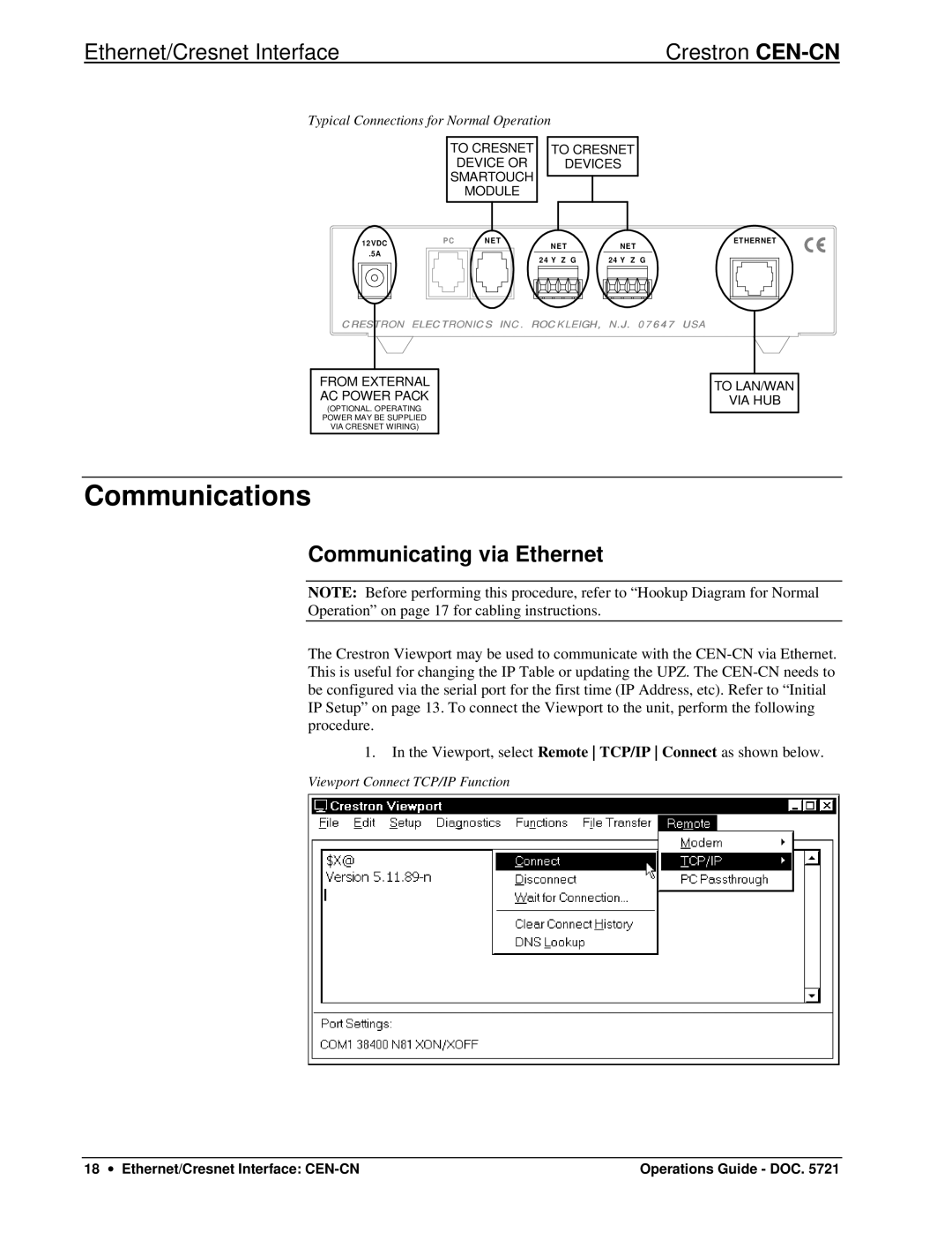
Typical Connections for Normal Operation |
|
TO CRESNET DEVICE OR SMARTOUCH MODULE
TO CRESNET
DEVICES
12VDC |
.5A |
P C | N E T |
|
| N E T | |
| 2 4 Y | Z G |
N E T |
2 4 Y Z G |
ETHERNET
CRESTRON ELECTRONICS INC. ROCKLEIGH, N.J. 07647 USA
FROM EXTERNAL AC POWER PACK
(OPTIONAL. OPERATING POWER MAY BE SUPPLIED VIA CRESNET WIRING)
TO LAN/WAN
VIA HUB
Communications
Communicating via Ethernet
NOTE: Before performing this procedure, refer to “Hookup Diagram for Normal
Operation” on page 17 for cabling instructions.
The Crestron Viewport may be used to communicate with the
1.In the Viewport, select Remote TCP/IP Connect as shown below.
Viewport Connect TCP/IP Function
18 ∙ Ethernet/Cresnet Interface: | Operations Guide - DOC. 5721 |
