CY7C1345G specifications
The Cypress CY7C1345G is a high-performance static random-access memory (SRAM) device designed for various applications requiring fast data access and minimal power consumption. As a member of Cypress's prolific family of SRAMs, the CY7C1345G is particularly noted for its performance in networking and telecommunications.This device features a 512 Kbit (64 K x 8) memory organization, making it suitable for applications needing moderate amounts of fast-access memory. The CY7C1345G operates at a wide voltage range of 2.7V to 3.6V, accommodating both high-performance and low-power applications. One of its standout attributes is its fast access time, with read cycle times as low as 10 ns, allowing for rapid data retrieval that is essential for modern computing requirements.
Another key feature of the CY7C1345G is its low-power operation mode, making it an excellent choice for battery-operated applications. It has a typical active current of only 35 mA and a standby current of just 3 µA, ensuring prolonged battery life while still maintaining high-performance levels. This low power consumption is complemented by the device's sleep mode functionality, which further reduces power draw during periods of inactivity.
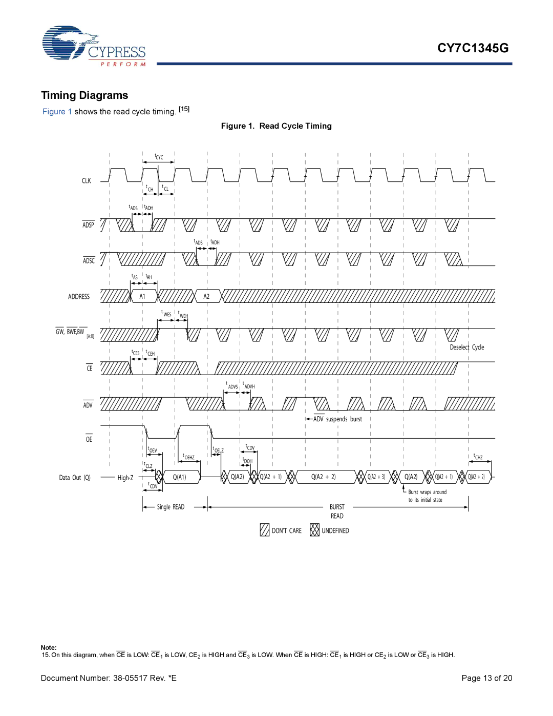
In terms of interface, the CY7C1345G employs a simple asynchronous access protocol, ensuring ease of integration into existing systems without the need for complex timing schemes. The device supports asynchronous read and write operations, with an output enable feature that facilitates efficient data retrieval.
The CY7C1345G is encased in a compact 44-pin TSOP II package, making it suitable for applications where space constraints are critical. Its design adheres to rigorous quality and reliability standards, with the device being fully tested to meet JEDEC specifications.
With its blend of speed, low power consumption, and simple interface, the Cypress CY7C1345G SRAM is ideal for a wide array of applications, including telecommunications systems, networking devices, and embedded systems. As technology drives the demand for faster and more efficient memory solutions, the CY7C1345G stands out as a reliable and versatile choice in the SRAM landscape.

