CONTENTS | REMARKS |
|
|
5.Control way of Error (if any)
1)“F1” error
Cause :
Check point : Measure the resistance between both terminals after separating CN8 (or CN15) of the Main PCB. (Refer to the
If
2)“R1” error
Cause :
Check point : Measure the resistance between both terminals after separating CN7 (or CN14) of the Main PCB. (Refer to the
If
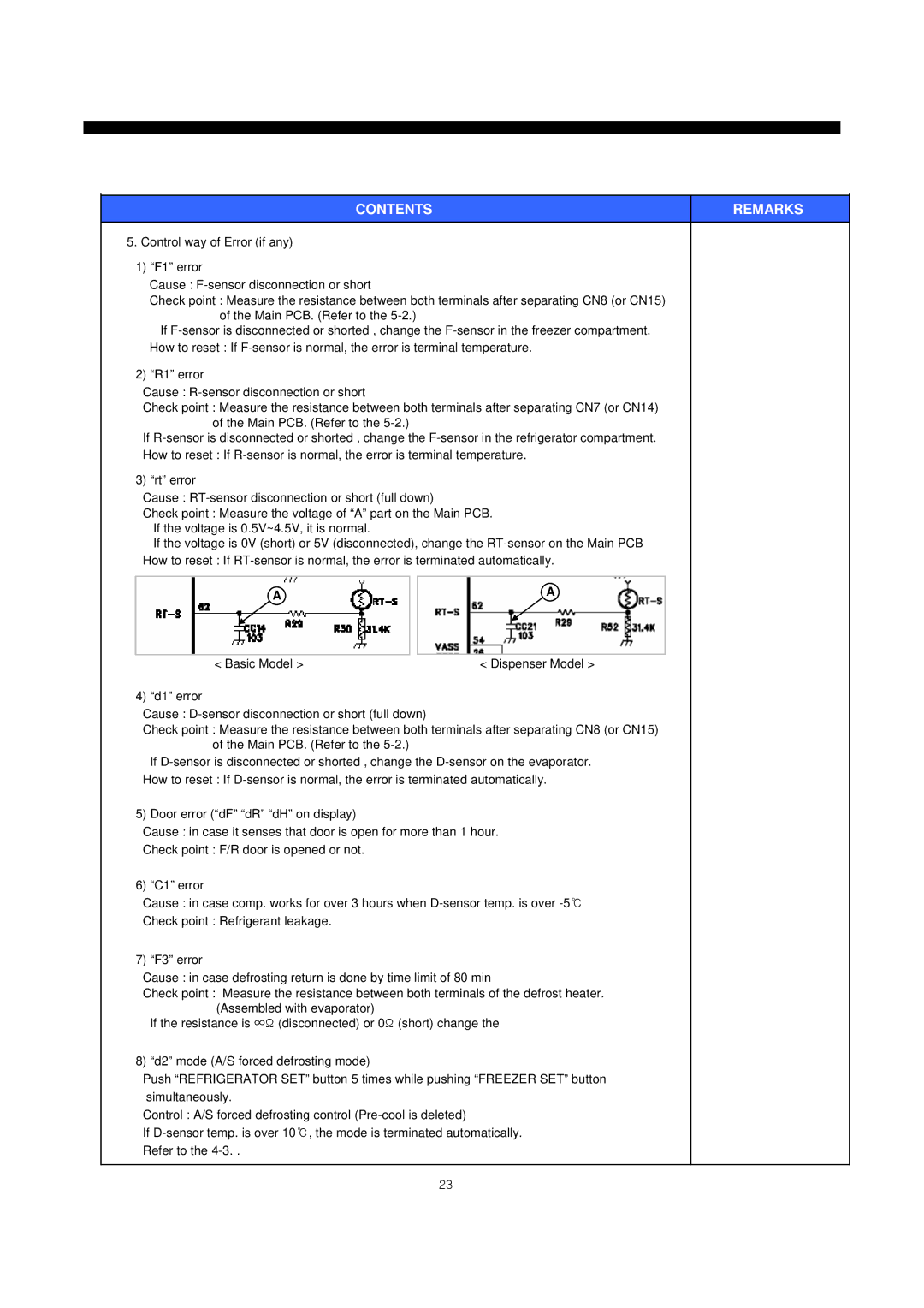
3) “rt” error
Cause :
Check point : Measure the voltage of “A” part on the Main PCB. If the voltage is 0.5V~4.5V, it is normal.
If the voltage is 0V (short) or 5V (disconnected), change the
A |
| A |
|
|
|
< Basic Model > |
| < Dispenser Model > |
4) “d1” error
Cause :
Check point : Measure the resistance between both terminals after separating CN8 (or CN15) of the Main PCB. (Refer to the
If
5) Door error (“dF” “dR” “dH” on display)
Cause : in case it senses that door is open for more than 1 hour.
Check point : F/R door is opened or not.
6) “C1” error
Cause : in case comp. works for over 3 hours when
Check point : Refrigerant leakage.
7) “F3” error
Cause : in case defrosting return is done by time limit of 80 min
Check point : Measure the resistance between both terminals of the defrost heater. (Assembled with evaporator)
If the resistance is ∞Ω (disconnected) or 0Ω (short) change the
8) “d2” mode (A/S forced defrosting mode)
Push “REFRIGERATOR SET” button 5 times while pushing “FREEZER SET” button simultaneously.
Control : A/S forced defrosting control
If
23
