5-3. Relay Function
- Basic Model
CONTENTS
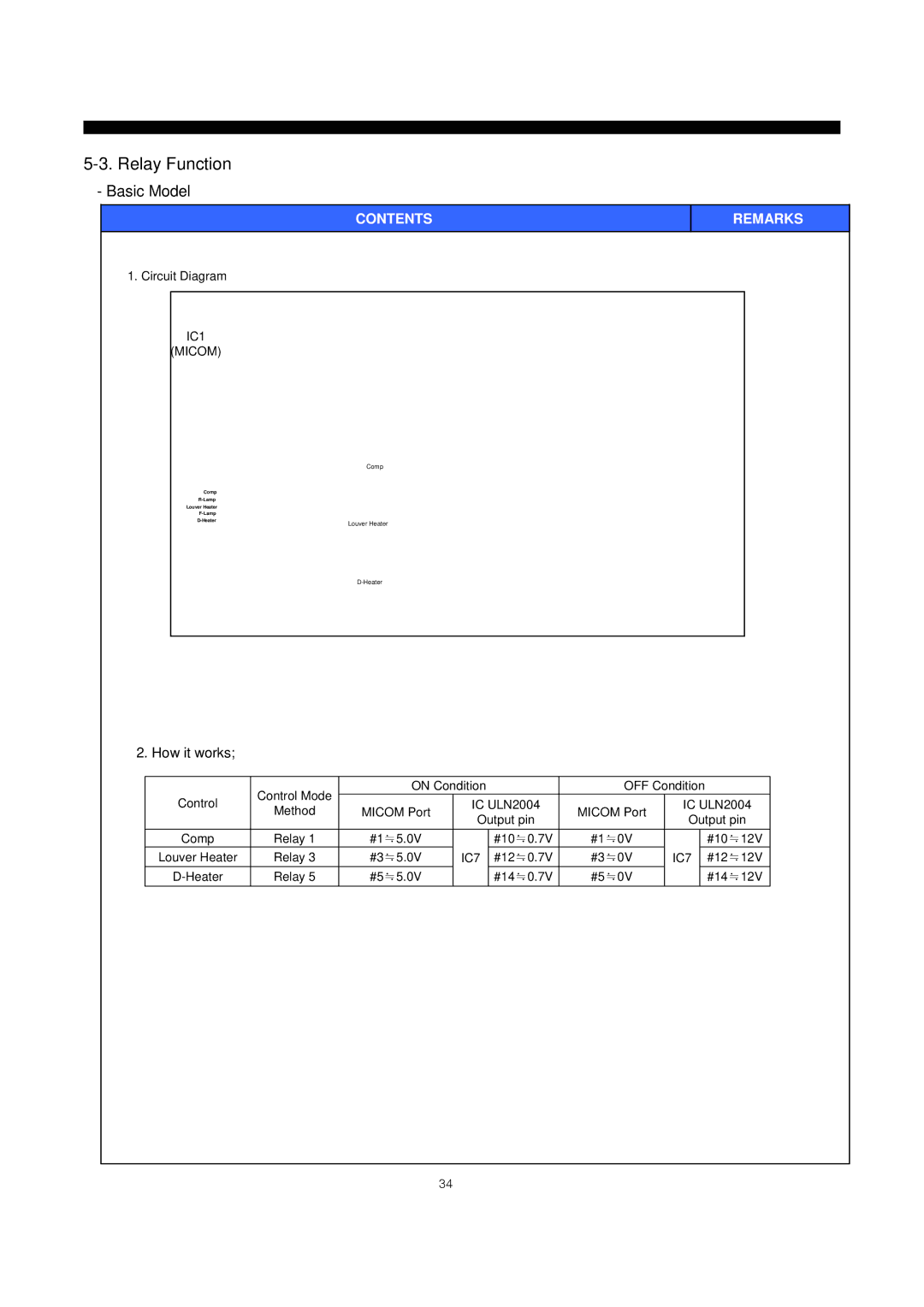
1. Circuit Diagram
IC1
(MICOM)
Comp
Comp
Louver Heater
|
|
|
| |
Louver Heater | ||||
|
| |||
|
|
|
|
|
|
|
| ||
REMARKS
2. How it works;
| Control Mode | ON Condition | OFF Condition | |||||
Control |
| IC ULN2004 |
| IC ULN2004 | ||||
Method | MICOM Port | MICOM Port | ||||||
| Output pin | Output pin | ||||||
|
|
|
| |||||
Comp | Relay 1 | #1≒5.0V |
| #10≒0.7V | #1≒0V |
| #10≒12V | |
Louver Heater | Relay 3 | #3≒5.0V | IC7 | #12≒0.7V | #3≒0V | IC7 | #12≒12V | |
Relay 5 | #5≒5.0V |
| #14≒0.7V | #5≒0V |
| #14≒12V | ||
34
