FREESTANDING INSTALLATION . . . continued
VERTICAL INSTALLATIONS: (Figures 19 - 24)
Your stove may be installed using many different vertical designs. Follow the same basic steps in locating your stove, attaching the exhaust system and outside air intake to your stove as described in "THROUGH THE WALL – DIRECT INSTALLATION" and the "PL" vent manufacturer's procedures for installing through a wall, ceiling, eve and roof.
COMMON, (but not inclusive), VERTICAL INSTALLATION DESIGNS ARE:
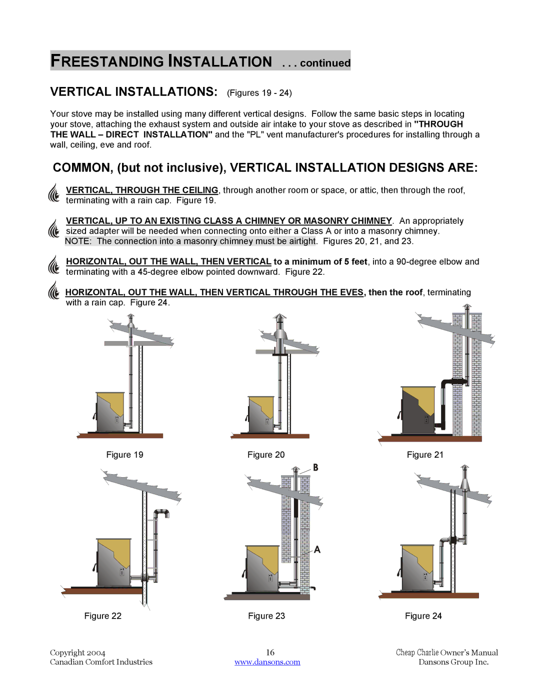
VERTICAL, THROUGH THE CEILING, through another room or space, or attic, then through the roof, terminating with a rain cap. Figure 19.
VERTICAL, UP TO AN EXISTING CLASS A CHIMNEY OR MASONRY CHIMNEY. An appropriately sized adapter will be needed when connecting onto either a Class A or into a masonry chimney. NOTE: The connection into a masonry chimney must be airtight. Figures 20, 21, and 23.
HORIZONTAL, OUT THE WALL, THEN VERTICAL to a minimum of 5 feet, into a
HORIZONTAL, OUT THE WALL, THEN VERTICAL THROUGH THE EVES, then the roof, terminating with a rain cap. Figure 24.![]()
Figure 19 | Figure 20 | Figure 21 |
B
A |
Figure 22 | Figure 23 | Figure 24 |
Copyright 2004 | 16 | Cheap Charlie Owner’s Manual |
Canadian Comfort Industries | www.dansons.com | Dansons Group Inc. |