IPP Bay View Insert / Built-In, FPP, IPP, FPP Freestanding, IPP, FPP specifications
Dansons Group is renowned for its innovative approach to outdoor and indoor heating solutions, especially with their FPP Freestanding and IPP Bay View Insert/Built-In models. These products are designed to cater to the diverse needs of homeowners seeking both functionality and aesthetics in their heating appliances.The FPP Freestanding model is a perfect blend of traditional charm and modern technology. It serves as an impressive centerpiece in any setting, providing warmth and ambiance to any space. One of its standout features is its large viewing area, which allows for an unobstructed view of the flames, creating a cozy and inviting atmosphere. It is equipped with advanced combustion technology that ensures efficient burning, maximizing heat output while minimizing emissions. This model is also designed to accommodate a range of fuel options, including wood and pellets, giving users the flexibility to choose what works best for them.
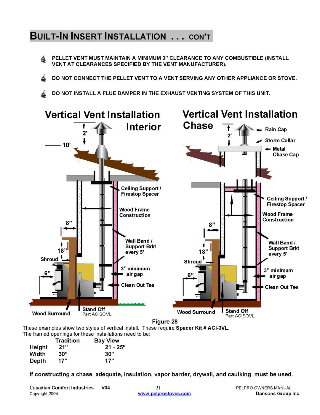
On the other hand, the IPP Bay View Insert/Built-In model offers a seamless integration into existing fireplaces or as a built-in feature in new constructions. This model emphasizes both performance and aesthetics, providing a sleek finish that enhances any room's decor. One of the key technologies in the IPP is its advanced blowers and distribution system, which efficiently circulates heat throughout the space, ensuring even warmth without hot spots. Additionally, the IPP incorporates a unique air-wash system that keeps the glass clean, allowing for a clear view of the flickering flames.
Both the FPP and IPP series prioritize ease of use and maintenance. They are designed with user-friendly controls that allow for easy operation and customization of heat settings. Moreover, Dansons Group emphasizes safety, incorporating features such as automatic shut-off mechanisms and cool-touch exteriors to prevent accidental burns.
In summary, the Dansons Group FPP Freestanding and IPP Bay View Insert/Built-In models stand out for their combination of aesthetic appeal, technological advancement, and user-friendly features. Whether you're looking for a statement piece or a practical heating solution, these products are designed to create a warm ambiance while ensuring efficiency and safety.

