24 | Datacom Systems Inc |
To connect the VERSAstream™
1.Two power supplies are provided. Use of the second power supply is strongly recommended to assure uninterrupted monitoring. Connect both power supply barrel connectors into the power 1 and 2 ports, respectively, of the VERSA- stream™. Plug the power supplies into the external power source, furthermore, connecting the second power supply to a different external power source circuit than the first power supply eliminates power as a single point of failure. The POWER 1 and 2 LEDs illuminate indicating power 1 and 2, respectively, are on. Either LED not illuminated indicates a defective power source and immediate replacement is required to insure redundant power integrity.
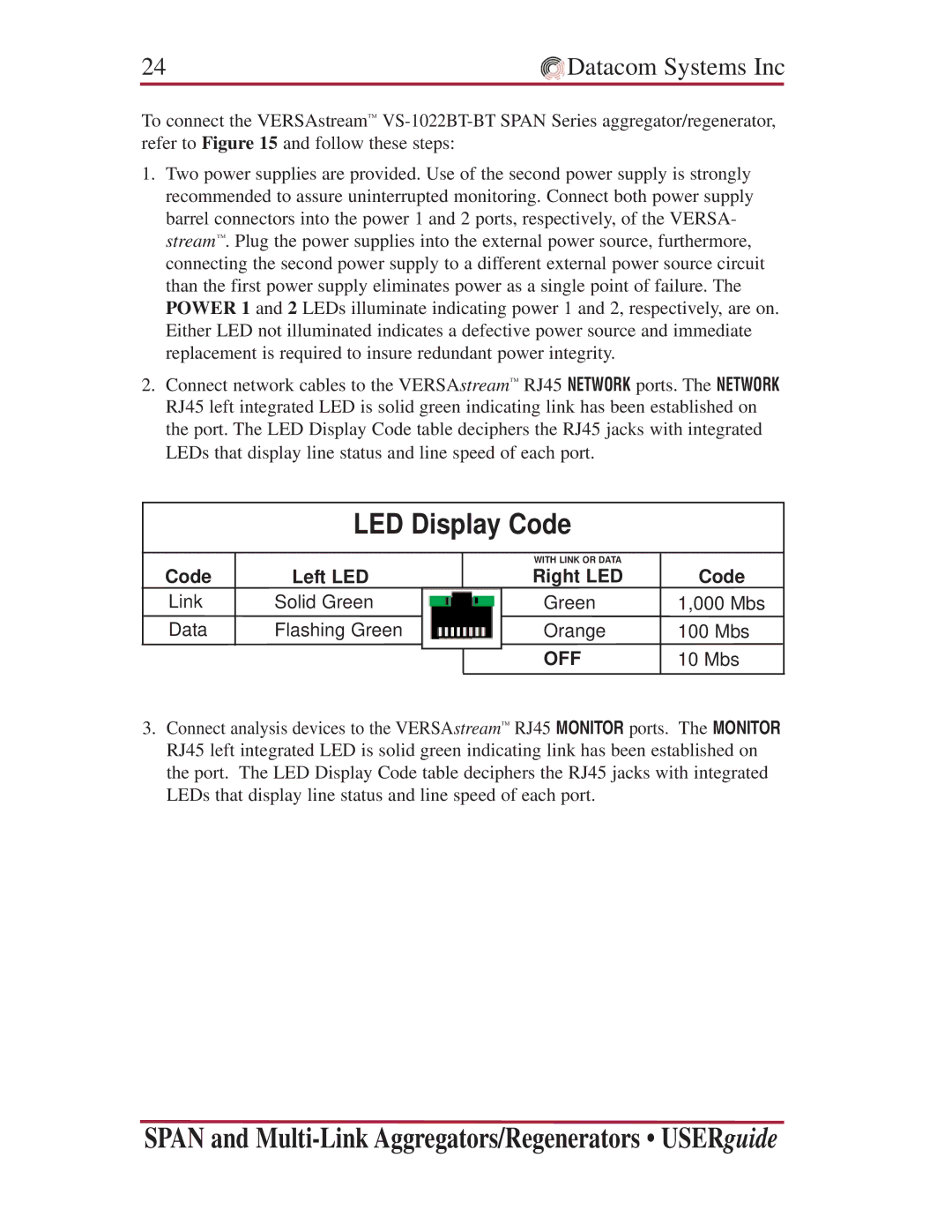
2.Connect network cables to the VERSAstream™ RJ45 NETWORK ports. The NETWORK RJ45 left integrated LED is solid green indicating link has been established on the port. The LED Display Code table deciphers the RJ45 jacks with integrated LEDs that display line status and line speed of each port.
LED Display Code
Code
Link Data
Left LED
Solid Green
Flashing Green
WITH LINK OR DATA
Right LED
Green
Orange
OFF
Code
1,000 Mbs
100Mbs
10Mbs
3.Connect analysis devices to the VERSAstream™ RJ45 MONITOR ports. The MONITOR RJ45 left integrated LED is solid green indicating link has been established on the port. The LED Display Code table deciphers the RJ45 jacks with integrated LEDs that display line status and line speed of each port.
SPAN and