30 | Datacom Systems Inc |
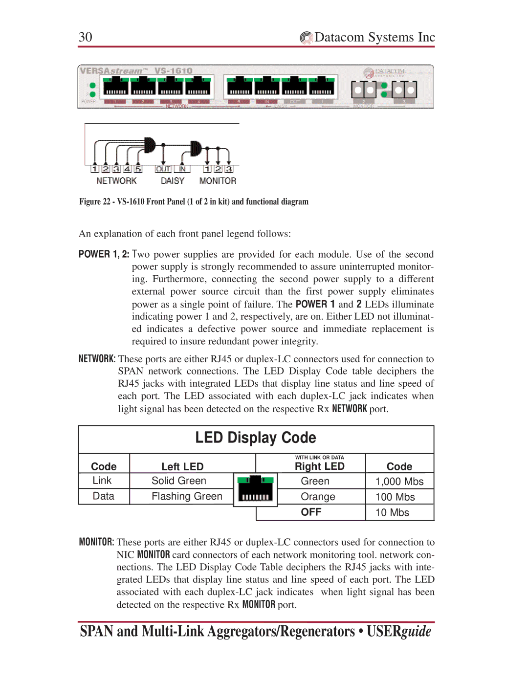
Figure 22 - VS-1610 Front Panel (1 of 2 in kit) and functional diagram
An explanation of each front panel legend follows:
POWER 1, 2: Two power supplies are provided for each module. Use of the second power supply is strongly recommended to assure uninterrupted monitor- ing. Furthermore, connecting the second power supply to a different external power source circuit than the first power supply eliminates power as a single point of failure. The POWER 1 and 2 LEDs illuminate indicating power 1 and 2, respectively, are on. Either LED not illuminat- ed indicates a defective power source and immediate replacement is required to insure redundant power integrity.
NETWORK: These ports are either RJ45 or
LED Display Code
Code
Link Data
Left LED
Solid Green
Flashing Green
WITH LINK OR DATA
Right LED
Green
Orange
OFF
Code
1,000 Mbs
100Mbs
10Mbs
MONITOR: These ports are either RJ45 or
SPAN and