4.Connect the chassis fan cable to the system board connector, FAN_SYS1 (see System Board Components).
5.Replace the computer cover (see Replacing the Computer Cover).
Processor Fan and Heat-Sink Assembly
WARNING: Despite having a plastic shield, the processor fan and
CAUTION: The processor fan and
Removing the Processor Fan and Heat-Sink Assembly
1.Follow the instructions in Before You Begin.
2.Remove the computer cover (see Removing the Computer Cover).
3.Disconnect the processor fan cable from the system board connector, FAN_CPU (see System Board Components).
4.Using a
CAUTION: When you remove the processor fan and
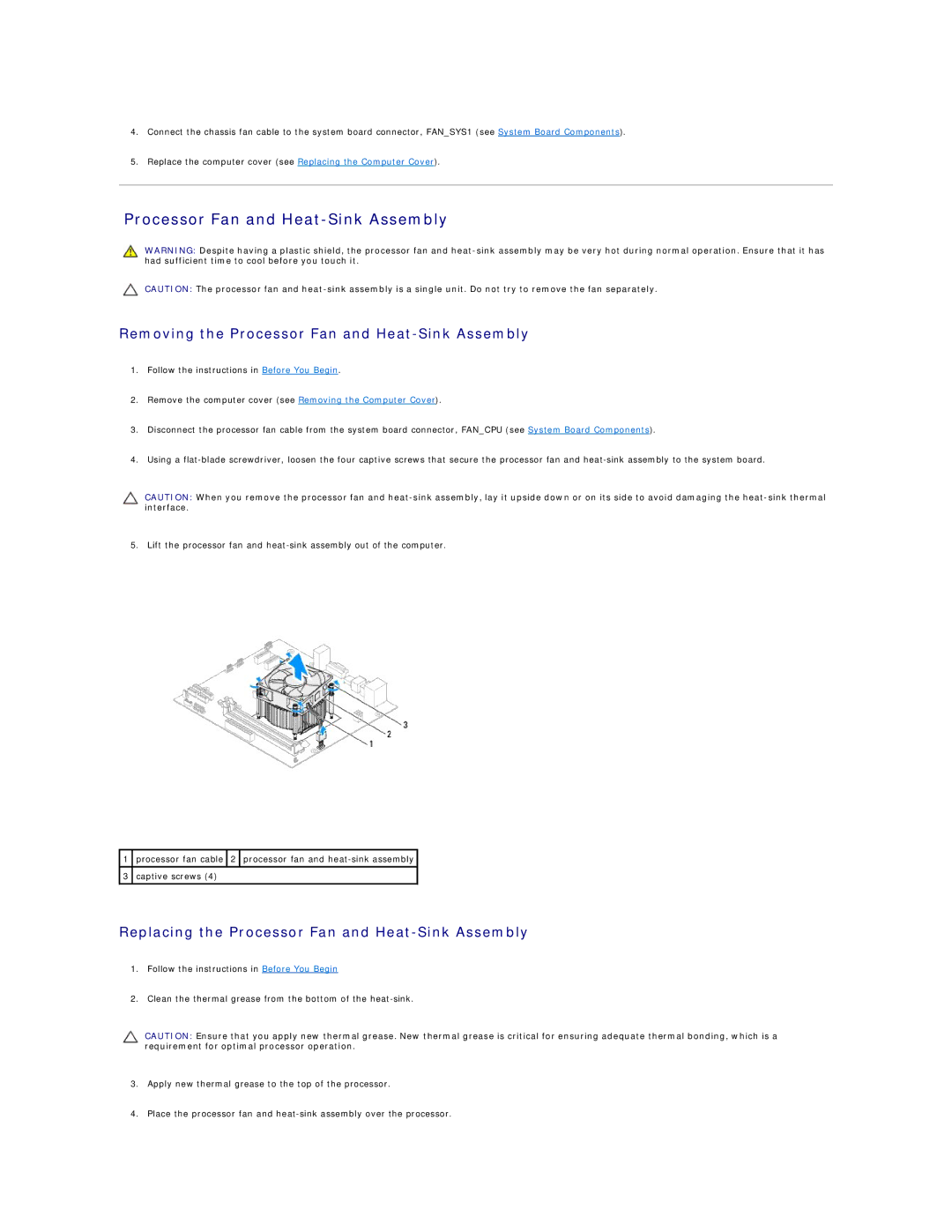
5. Lift the processor fan and
1processor fan cable ![]() 2
2 ![]() processor fan and
processor fan and
3captive screws (4)
Replacing the Processor Fan and Heat-Sink Assembly
1.Follow the instructions in Before You Begin
2.Clean the thermal grease from the bottom of the
CAUTION: Ensure that you apply new thermal grease. New thermal grease is critical for ensuring adequate thermal bonding, which is a requirement for optimal processor operation.
3.Apply new thermal grease to the top of the processor.
4.Place the processor fan and