aInstall a cable from cluster node 2 HBA port 0 to
bInstall a cable from cluster node 2 HBA port 1 to
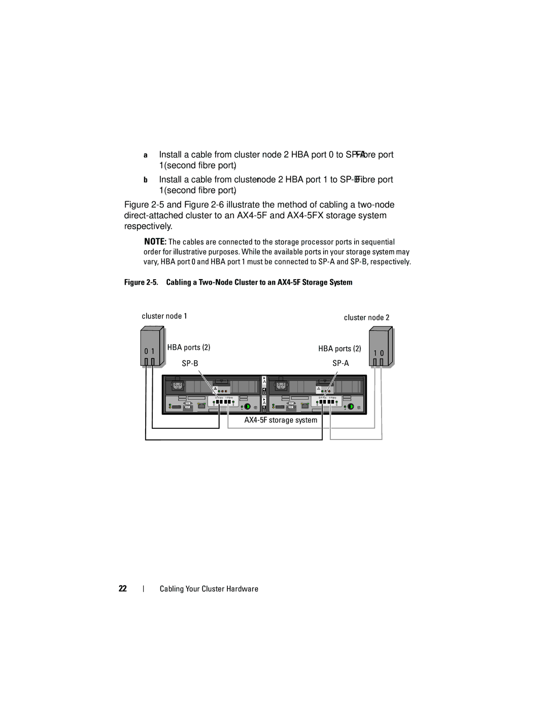
Figure 2-5 and Figure 2-6 illustrate the method of cabling a two-node direct-attached cluster to an AX4-5F and AX4-5FX storage system respectively.
NOTE: The cables are connected to the storage processor ports in sequential order for illustrative purposes. While the available ports in your storage system may vary, HBA port 0 and HBA port 1 must be connected to
Figure 2-5. Cabling a Two-Node Cluster to an AX4-5F Storage System
cluster node 1 | cluster node 2 |
0 1 |
HBA ports (2) | HBA ports (2) |
|
| A |
|
|
| B |
|
0 Fibre | 1 Fibre | 0 | 1 Fibre |
|
| A |
|
|
| B |
|
AX4-5F storage system
1 0 |
22
