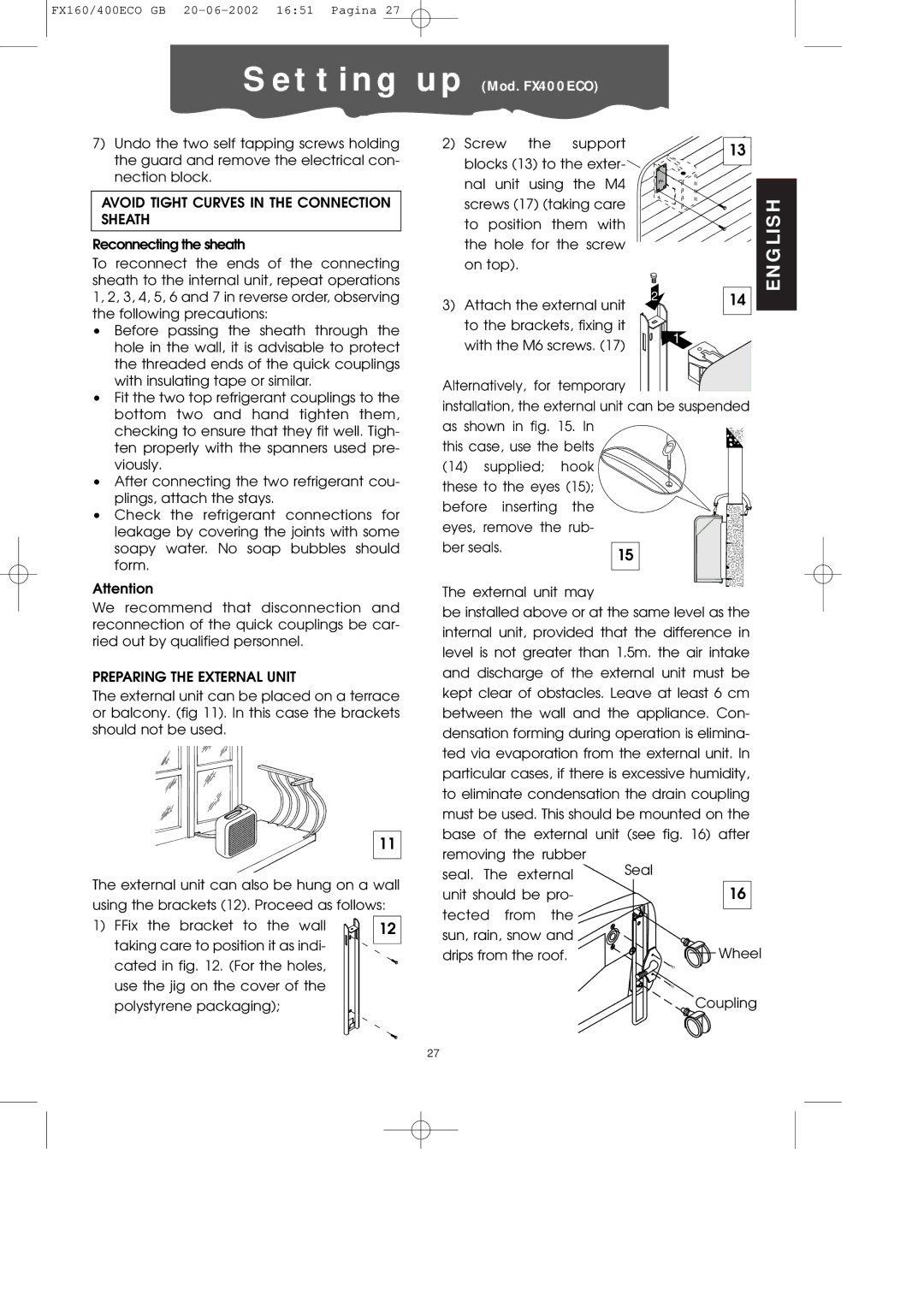
FX400ECO specifications
The DeLonghi FX400ECO is a remarkable addition to the world of kitchen appliances, particularly focused on the cooking sector. Designed with eco-conscious consumers in mind, this air fryer stands out for its innovative features and advanced technologies that allow for healthier cooking without compromising on taste.One of the main highlights of the FX400ECO is its unique Eco-Design. This appliance is crafted with sustainability at its core, boasting energy-efficient elements that contribute to a lower carbon footprint. The device employs advanced heating technology that ensures rapid heat distribution, allowing meals to be cooked evenly and efficiently. This not only saves time but also minimizes energy consumption, making it a great choice for environmentally aware households.
The FX400ECO features an intuitive digital control panel that makes it user-friendly, providing precise temperature settings and cooking times. Users can select from various cooking modes, including frying, baking, and grilling, which caters to a wide range of culinary preferences. The versatile temperature range allows for culinary creations from crispy fries to succulent roasted vegetables.
Another key characteristic of the DeLonghi FX400ECO is its capacity. With a generous cooking bowl, it can accommodate meals for the entire family, making it ideal for gatherings or everyday cooking. The removable parts are dishwasher-safe, enhancing convenience and ease of cleaning, further complementing the user-friendly design.
Incorporating cutting-edge technologies, the FX400ECO utilizes a proprietary air circulation system that cooks food using a fraction of the oil compared to traditional frying methods. This results in lighter, healthier versions of beloved dishes, reducing fat and calories while maintaining flavor and texture.
Safety features are also paramount in the design of the FX400ECO. It includes an automatic shut-off function that activates if the appliance is tipped or mishandled, ensuring peace of mind during usage. The sleek design combines aesthetic appeal with functionality, allowing it to blend seamlessly into modern kitchens.
In summary, the DeLonghi FX400ECO is an eco-friendly, multi-functional air fryer that combines innovative cooking technologies with ease of use and safety features. Its focus on sustainability, coupled with the ability to produce healthier meals without compromising taste, makes it a valuable device for anyone looking to enhance their cooking experience while aligning with environmentally responsible practices.

