MOVING TABLE TO THE 90 DEGREE CUT-OFF POSITION
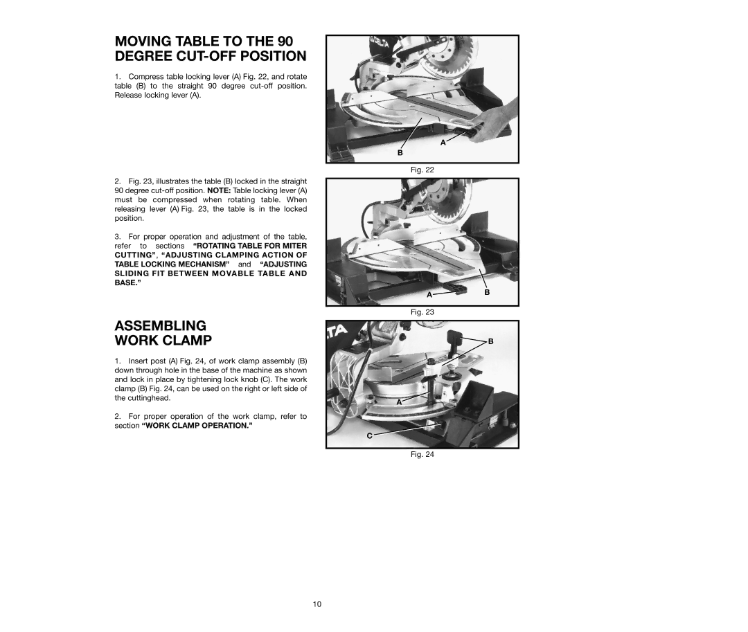
1.Compress table locking lever (A) Fig. 22, and rotate table (B) to the straight 90 degree
2.Fig. 23, illustrates the table (B) locked in the straight
90degree cut-off position. NOTE: Table locking lever (A) must be compressed when rotating table. When releasing lever (A) Fig. 23, the table is in the locked position.
3.For proper operation and adjustment of the table, refer to sections “ROTATING TABLE FOR MITER CUTTING”, “ADJUSTING CLAMPING ACTION OF
TABLE LOCKING MECHANISM” and “ADJUSTING
SLIDING FIT BETWEEN MOVABLE TABLE AND BASE.”
ASSEMBLING
WORK CLAMP
1.Insert post (A) Fig. 24, of work clamp assembly (B) down through hole in the base of the machine as shown and lock in place by tightening lock knob (C). The work clamp (B) Fig. 24, can be used on the right or left side of the cuttinghead.
2.For proper operation of the work clamp, refer to section “WORK CLAMP OPERATION.”
A
B
Fig. 22
A![]() B
B
Fig. 23
B
A![]()
C
Fig. 24
10
