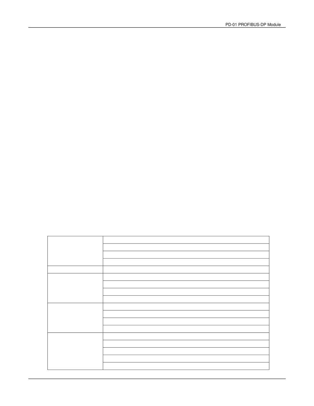
Default settings of PZD structure
STW1: Control Word, mapping to MODBUS address 0x2000 of VFD series Drives.
HSW: Main set point, mapping to MODBUS address 0x2001 of VFD series Drives.
ZSW: Drives status, mapping to MODBUS address 0x2101 of VFD series Drives.
HIW: Main command frequency, mapping to MODBUS address 0x2102 of VFD series Drives.
DP master
PZD3: No default assignment
PZD4: No default assignment
VFD series
PZD3: Output frequency, mapping to MODBUS address 0x2103 of VFD series Drives.
PZD4: Output current, mapping to MODBUS address 0x2104 of VFD series Drives.
Control and Status words
Control word (data from DP to VFD series Drives)
|
| 00: No function |
|
|
| 01: Stop |
|
| |
| 10: Run |
|
| |
|
|
|
| |
|
| 11: JOG+Run |
|
|
| Not used |
|
| |
|
| 00: No function |
|
|
| 01: FWD |
|
| |
| 10: REV |
|
| |
|
|
|
| |
|
| 11: Change direction |
| |
|
| 00: 1st Accel / Decel time |
| |
| 01: 2nd Accel / Decel time |
| ||
| 10: 3rd Accel / Decel time |
| ||
|
|
| ||
|
| 11: 4th Accel / Decel time |
| |
|
| 0000: Main speed |
|
|
| 0001: 1st speed |
|
| |
| 0010: 2nd speed |
|
| |
|
| 0011: 3rd speed |
|
|
|
| 0100: 4th speed |
|
|
|
|
|
|
|
DELTA ELECTRONICS, INC. ALL RIGHTS RESERVED | 13 |
| ||