PD-01 PROFIBUS-DP Module
Chapter 6 Troubleshooting
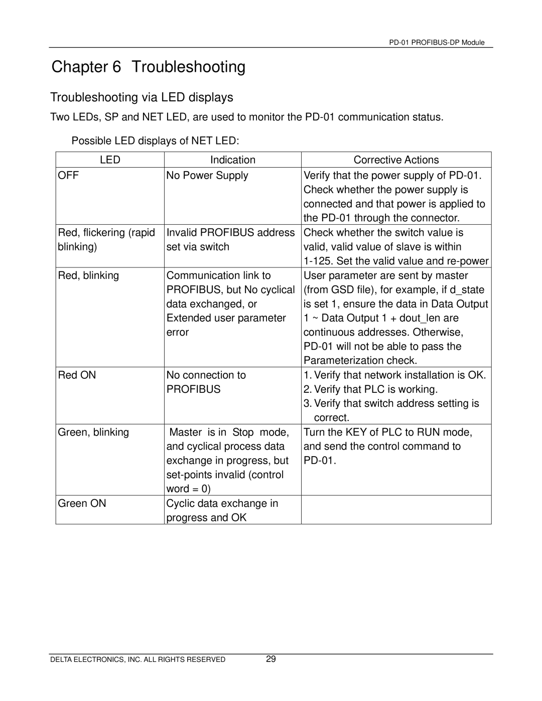
Troubleshooting via LED displays
Two LEDs, SP and NET LED, are used to monitor the
Possible LED displays of NET LED:
LED | Indication | Corrective Actions |
OFF | No Power Supply | Verify that the power supply of |
|
| Check whether the power supply is |
|
| connected and that power is applied to |
|
| the |
Red, flickering (rapid | Invalid PROFIBUS address | Check whether the switch value is |
blinking) | set via switch | valid, valid value of slave is within |
|
| |
Red, blinking | Communication link to | User parameter are sent by master |
| PROFIBUS, but No cyclical | (from GSD file), for example, if d_state |
| data exchanged, or | is set 1, ensure the data in Data Output |
| Extended user parameter | 1 ~ Data Output 1 + dout_len are |
| error | continuous addresses. Otherwise, |
|
| |
|
| Parameterization check. |
Red ON | No connection to | 1. Verify that network installation is OK. |
| PROFIBUS | 2. Verify that PLC is working. |
|
| 3. Verify that switch address setting is |
|
| correct. |
Green, blinking | “Master” is in “Stop” mode, | Turn the KEY of PLC to RUN mode, |
| and cyclical process data | and send the control command to |
| exchange in progress, but | |
|
| |
| word = 0) |
|
Green ON | Cyclic data exchange in |
|
| progress and OK |
|
DELTA ELECTRONICS, INC. ALL RIGHTS RESERVED | 29 |