| 0101: 5th speed | |
| 0110: 6th speed | |
| 0111: 7th speed | |
| 1000: 8th speed | |
1001: 9th speed | ||
1010: 10th speed | ||
| 1011: 11th speed | |
| 1100: 12th speed | |
| 1101: 13th speed | |
| 1110: 14th speed | |
| 1111: 15th speed | |
b12 | 1: Enable | |
| 00: No function | |
01:Operation command controlled by PU | ||
10:Operation command by Pr. setting | ||
| ||
| 11:Switch between PU and Pr. setting | |
b15 | Not used |
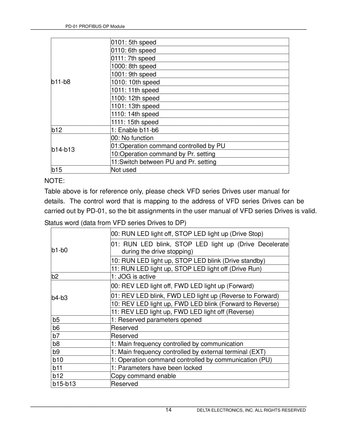
NOTE:
Table above is for reference only, please check VFD series Drives user manual for
details. The control word that is mapping to the address of VFD series Drives can be carried out by
Status word (data from VFD series Drives to DP)
|
| 00: RUN LED light off, STOP LED light up (Drive Stop) |
| |
|
|
|
| |
| 01: RUN LED blink, STOP LED light up (Drive Decelerate |
| ||
| during the drive stopping) |
|
| |
|
| 10: RUN LED light up, STOP LED blink (Drive standby) |
| |
|
| 11: RUN LED light up, STOP LED light off (Drive Run) |
| |
| b2 | 1: JOG is active |
|
|
|
| 00: REV LED light off, FWD LED light up (Forward) |
| |
|
|
|
| |
| 01: REV LED blink, FWD LED light up (Reverse to Forward) |
| ||
|
| 10: REV LED light up, FWD LED blink (Forward to Reverse) |
| |
|
| 11: REV LED light up, FWD LED light off (Reverse) |
| |
| b5 | 1: Reserved parameters opened |
| |
| b6 | Reserved |
|
|
| b7 | Reserved |
|
|
| b8 | 1: Main frequency controlled by communication |
| |
| b9 | 1: Main frequency controlled by external terminal (EXT) |
| |
| b10 | 1: Operation command controlled by communication (PU) |
| |
| b11 | 1: Parameters have been locked |
| |
| b12 | Copy command enable |
|
|
| Reserved |
|
| |
|
|
|
|
|
|
| 14 | DELTA ELECTRONICS, INC. ALL RIGHTS RESERVED | |