DeviceNet Network Scanner
Open the DIN rail clip on
Clip up the DIN rail clips on
DVPDNET
DVP28SV
35mm DIN rail
RUN
STOP
3.3Connecting to DeviceNet Connection Port
The colors on the PINs on the DeviceNet connection port match the colors of the connection cables. Make sure you connect the cable to the right PIN.
We recommend you also apply Delta’s power module in the connection.
4 Configuration
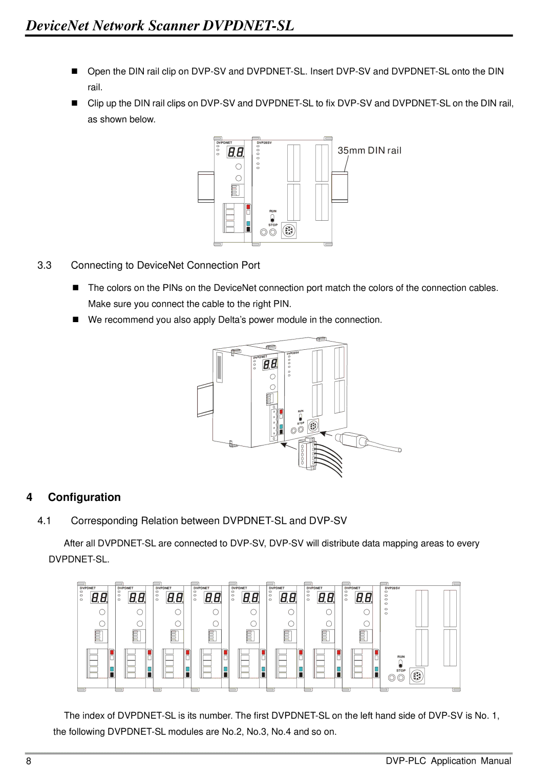
4.1Corresponding Relation between DVPDNET-SL and DVP-SV
After all
DVPDNET-SL.
DVPDNET | DVPDNET | DVPDNET | DVPDNET | DVPDNET | DVPDNET | DVPDNET | DVPDNET | DVP28SV |
RUN
STOP
The index of
8 |