DeviceNet Network Scanner
3. | Power, MS, NS LED | 8. | Function switch |
4. | DIN rail clip | 9. | DeviceNet connection port |
5.Digital indicator
2.3DeviceNet Connection Port
The connector is used on the connection to DeviceNet. Wire by using the connector enclosed with
DVPDNET-SL.
PIN | Signal | Color | Content |
|
1 | V- | Black | 0 VDC | 5 |
2 | CAN_L | Blue | Signal- | 4 |
3 | SHIELD | - | Shielded | 3 |
2 | ||||
4 | CAN_H | White | Signal+ | 1 |
5 | V+ | Red | 24 VDC |
|
2.4Address Switch
The switch is used on setting up the node address of
Switch setting | Content |
|
|
0 … 63 | Valid DeviceNet node address |
|
|
64…99 | Invalid DeviceNet node address |
|
|
5
4 3
2 |
|
1 | 0 |
| |
4 | 5 |
| |
3 |
|
2 |
|
1 | 0 |
|
6
7
8 9
6
7
8 9
Example: If you need to set the node address of
Note:
zPlease set up the node address when the power is switched off. After the setup is completed,
DVPDNET-SL.
zWhen
zUse slotted screwdriver to rotate the switch carefully in case you scratch the switch.
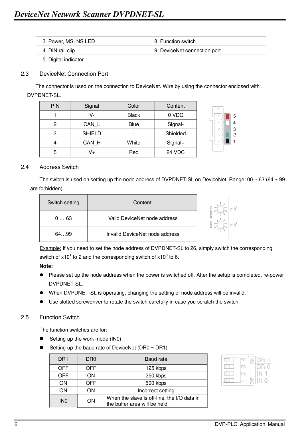
2.5Function Switch
The function switches are for:
Setting up the work mode (IN0)
Setting up the baud rate of DeviceNet (DR0 ~ DR1)
DR1 | DR0 | Baud rate | |
|
|
| |
OFF | OFF | 125 kbps | |
OFF | ON | 250 kbps | |
ON | OFF | 500 kbps | |
ON | ON | Incorrect setting | |
IN0 | ON | When the slave is | |
the buffer area will be held. | |||
|
|
6 |