DeviceNet Network Scanner
| OFF | When the slave is |
| the buffer area will be cleared. | |
|
| |
IN1 |
| Reserved |
|
|
|
Note:
zPlease set up the function switch when the power is switched off. After the setup is completed,
DVPDNET-SL.
zWhen
zUse slotted screwdriver to adjust the DIP switch carefully in case you scratch the switch.
2.6Digital Indicator
The digital indicator provides the following two functions:
DVPDNET
POWER
MS
NS
1.Displaying the node address and error messages of
2.Displaying the error message of slave.
2.7Extension Port
The extension port is used on connecting
3Basic Operation
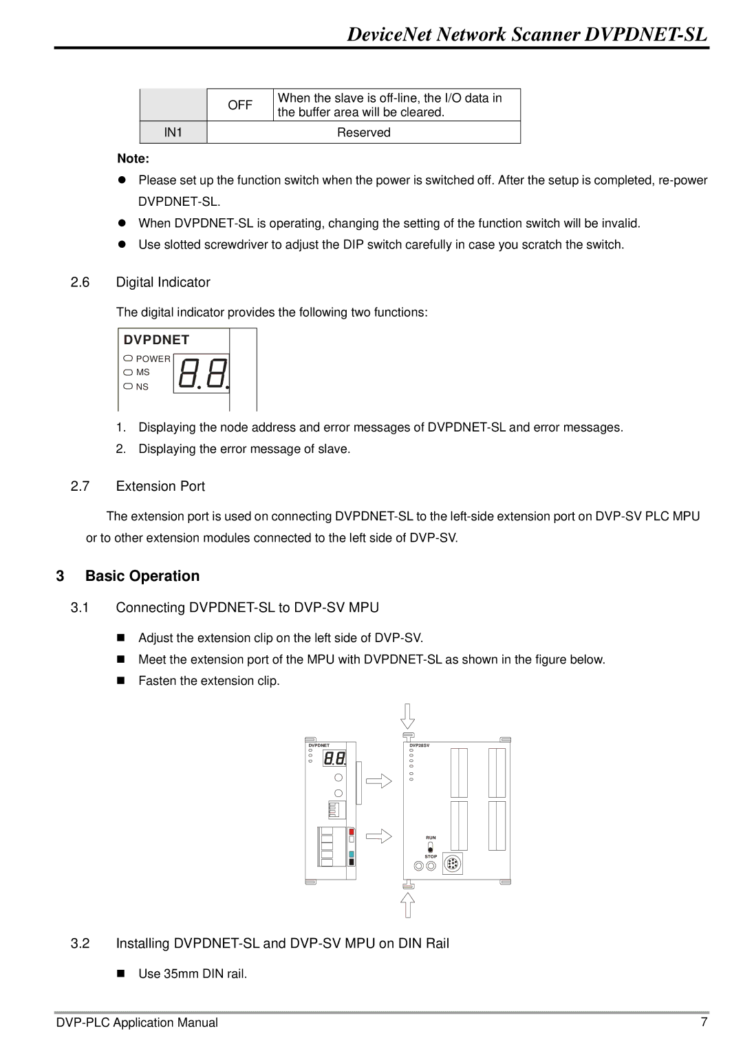
3.1Connecting
Adjust the extension clip on the left side of
Meet the extension port of the MPU with
Fasten the extension clip.
DVPDNET | DVP28SV |
RUN
STOP
3.2Installing DVPDNET-SL and DVP-SV MPU on DIN Rail
Use 35mm DIN rail.
7 |