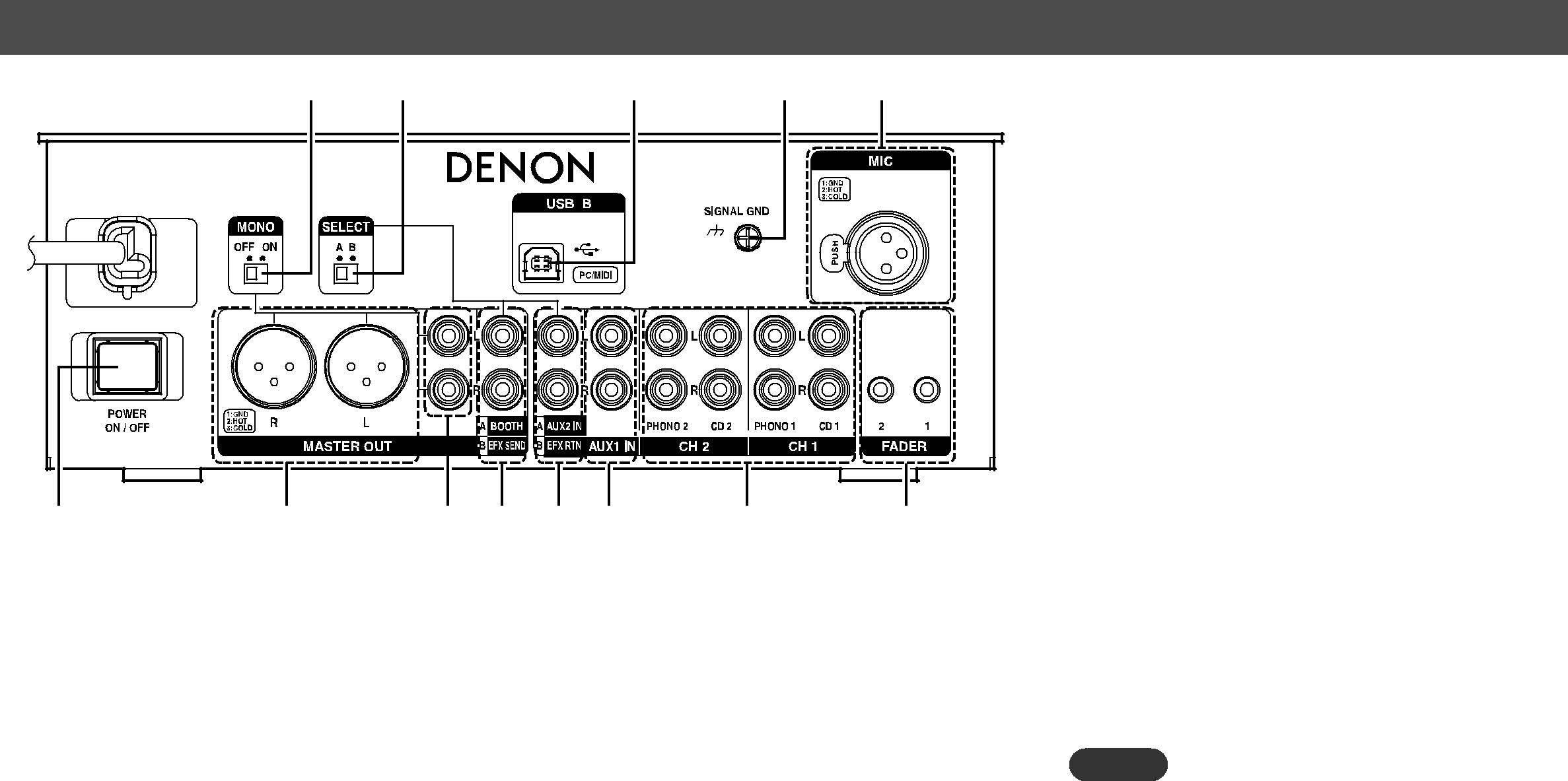
Rear panel
Q3 Q2 | Q1 | Q0 o |
q | w | e r t y | u | i |
qPower switch (POWER)································ (9)
wMaster output (balanced) terminal (MASTER OUT)·············································· (7)
Pin layout:
1.Ground (GND)
2.Hot (HOT)
3.Cold (COLD)
Suitable connector:
Cannon
eMaster output (unbalanced) terminal (MASTER OUT)·············································· (7)
rBooth/Effect send output terminal (BOOTH/EFX SEND)································· (7, 8)
SEND (Output) :
•Connect to the input terminal of an external effect processor.
BOOTH (Output) :
•Connect to the input terminal of an active speaker.
tAUX2/Effect return input terminal
(AUX2 IN/EFX RTN)·································· (6, 8)
RETURN (Input):
•Connect to the output terminal of an external effect processor.
AUX2 (Input):
•Connect to the output terminal of an external device.
yAudio input terminal (AUX1 IN)·················· (6)
uAudio input terminal (CH1, CH2)················· (6) Connect a device such as an MM (Moving Magnet) cartridge turntable (RIAA) or CD player.
iFader output terminal
(FADER1, 2)·············································· (6, 12) Connect these terminals to the Fader input terminals of the
oMIC input terminal (MIC)
Connect a microphone to this balanced combo jack using an XLR connector.
Pin layout:
1.Ground (GND)
2.Hot (HOT)
3.Cold (COLD)
Suitable connector:
Cannon
Q0Signal earth terminal (SIGNAL GND)·········· (6) Q1USB B terminal (USB B)························· (8, 15)
Q2Input/Output mode selection switch (SELECT A, B)············································ (7, 8) Selects between the r and t terminal functions.
NOTE
The input and output volume levels are different for the input mode (SELECT) settings (A or B). Set the correct level to match the connected device.
Q3Monaural output selection switch (MONO)·························································· (7) When ”ON”, mixed monaural audio is outputted from the L and R terminals for XLR and RCA Master outputs.
5