VENTING INSTALLATION
VENTING INSTALLATION
9
A
The following section is provided as a guide to a standard
Standing codes requirements concerning
This gas appliance must be vented to the outdoors only and may not be terminated into an attic space or into a chimney flue servicing a
This appliance may be vented through a manufactured chimney system or a masonry chimney using a
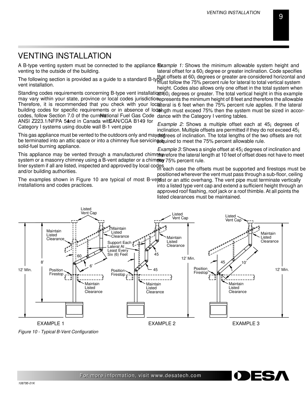
The examples shown in Figure 10 are typical of most
Example 1: Shows the minimum allowable system height and lateral offset for a 60° degree or greater inclination. Code specifies that offsets at 60° degrees or greater are considered horizontal and must follow the 75% percent rule for lateral to total vertical system height. Codes also allows only one offset in the total system when at 60° degrees or greater. The total vertical height in this example represents the minimum height of 8 feet and therefore the allowable lateral is 6 feet when the 75% percent rule applies. If the lateral length must exceed 75% then the system must be sized in accor- dance with the Category I venting tables.
Example 2: Shows a multiple offset each at 45° degrees of inclination. Multiple offsets are permitted if they do not exceed 45° degrees of inclination. The total lengths of the two offsets are not required to meet the 75% percent allowable rule.
Example 3: Shows a single offset at 45° degrees of inclination and therefore the lateral length at 10 feet of offset does not have to meet the 75% percent rule.
In each case the offsets must be supported and firestops must be positioned wherever the vent must pass through a
|
| Listed |
|
|
|
|
|
|
| Vent Cap |
|
| Listed | Listed | |
|
|
|
|
| Vent Cap | ||
|
|
|
|
| Vent Cap | ||
|
|
|
|
|
| ||
| Maintain |
| Maintain |
|
|
|
|
|
| Listed |
|
|
| Maintain | |
| Listed |
|
|
|
| ||
|
| Clearance |
| Maintain |
| Listed | |
| Clearance |
|
|
| |||
|
| Support Each |
| Listed |
| Clearance | |
|
|
|
|
| |||
|
|
| Lateral At |
| Clearance |
|
|
|
|
| Least Every | 45° |
|
|
|
|
| 60° | Six (6) Feet | 12' Min. |
|
| |
|
|
|
|
|
| ||
| 8' |
|
|
| 45° | 10' | |
| 6' |
|
|
| |||
12' Min. | Position |
| 45° | Position |
| 12' Min. | |
| Position |
| |||||
| Firestop |
| Firestop |
| Firestop |
|
|
|
|
|
|
|
| ||
|
| Maintain |
| Maintain |
|
| Maintain |
|
| Listed |
| Listed |
|
| Listed |
|
| Clearance |
| Clearance |
|
| Clearance |
EXAMPLE 1 | EXAMPLE 2 | EXAMPLE 3 |
Figure 10 - Typical B-Vent Configuration
![]()
![]()
![]()
![]() For more information, visit www.desatech.com
For more information, visit www.desatech.com