Manuals
/
Desa
/
Household Appliance
/
Indoor Fireplace
Desa
CD36TN-M Installing optional blower accessories, Blower Model BK, Attaching Speed Control to
Models:
CD36TN-M
1
19
44
44
Download
44 pages
7.76 Kb
16
17
18
19
20
21
22
23
Troubleshooting
Install
Parts list
Wiring Diagrams
Warranty
Dimension
Observed Problem
Manual Lighting Procedure
Cleaning and Maintenance
Held Remote Control Unit
Page 19
Image 19
Page 18
Page 20
Page 19
Image 19
Page 18
Page 20
Contents
WHAT TO DO IF YOU SMELL GAS
Table of Contents
Safety Information
Product Identification
Safety information
Continued
Location and space requirements
Product Features
Pre-Installation Preparation
Local Codes
Clearances
Figure 3 - Fireplace Bottom Dimensions
Continued
Packaging and Removal
Figure 5 - Framing Clearances for Corner
Installation
Figure 6 - Unit Dimensions
Continued
MANTEL CLEARANCES
Continued
Outside Corner
D E B L
Figure 9 - Minimum Clearances for Termination Cap
Inside Corner
Venting Installation Instructions
Figure 10 - Vent Pipe Connections
Venting Installation instructions
INSTALLATION PLANNING
Continued
Standoff Vent Cap Apply Mastic to All Four Sides
Figure 12 - Installing Siding Standoff
Figure 13 - Installing Outer Wall Firestop
Inner Wall Firestop
Clearance at Ground Floor Installation
Configuration For Corner Installation
Using One 90 Elbow
Configuration with Vertical Rise and One 90 Elbow
Continued
HORIZONTAL VENT INSTALLATIONS
Continued
Installation for vertical termination
Flat Ceiling Installation
Figure 20 - Installing Firestop
Continued
Thimble Installation
Vertical Termination Configurations for Top Vent
Figure 21 - Installing Thimble with Firestop
Figure 23 - Vertical Venting
parts list for venting kits and components
Configuration Using Two 90 Elbows
Continued
Description
Continued
ELECTRICAL SUPPLY CONNECTION
Number
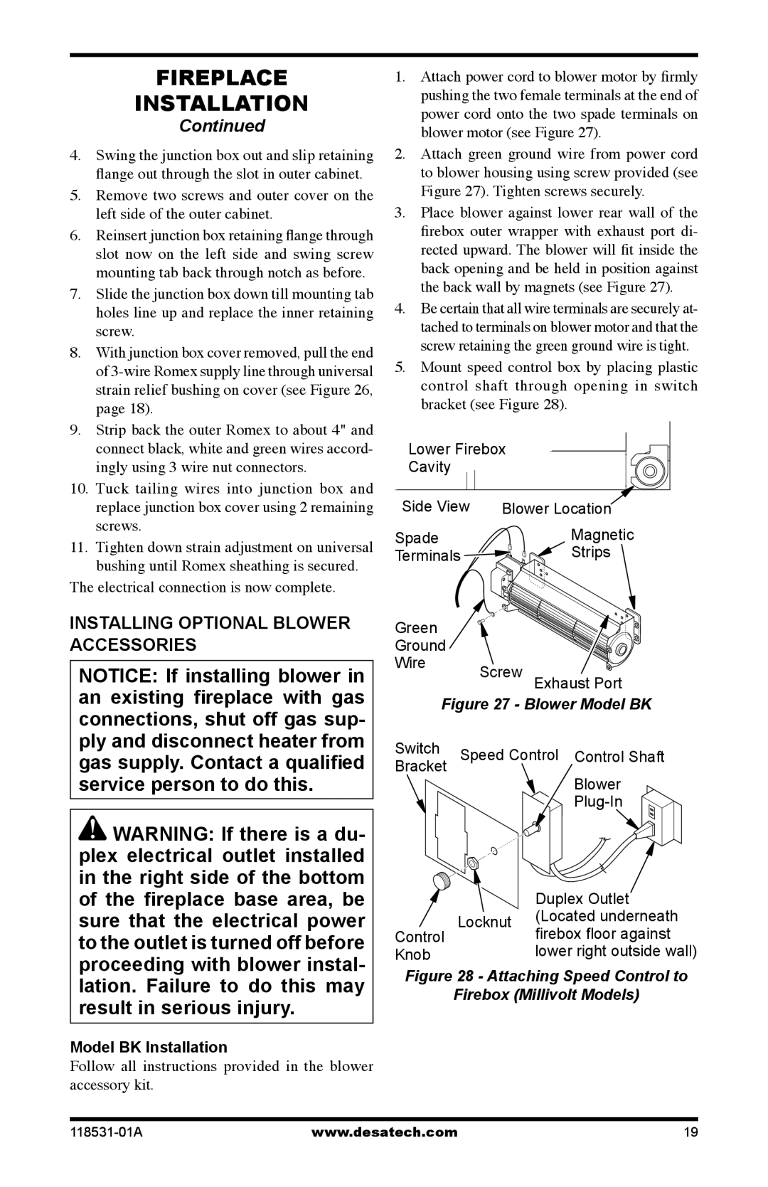
Firebox Millivolt Models
Installing optional blower accessories
Figure 27 - Blower Model BK
Figure 28 - Attaching Speed Control to
Continued
Model BKT Installation
Figure 30 - Blower Model BKT
Continued
Wiring Diagrams
Figure 31 - Blower Wiring Diagram for
Figure 32 - Millivolt Ignition Wiring Diagram
Figure 34 - Attaching Alkaline Battery to
Installing optional wall Mount Switch - gwmS2
Figure 33 - Connecting Wall Switch to
Installing Remote Receiver
Check Gas Type
Installing Gas Piping to Fireplace Location
Installation Items Needed
Continued
Pressure Testing Gas Supply Piping System
CONNECTING FIREPLACE TO GAS SUPPLY
Installation Items Needed
Figure 39 - Connecting Flexible Gas Line
Natural Gas Fireplace
Removing/Replacing Glass Door
Figure 40 - Equipment Shutoff Valve
Figure 42 - Checking Gas Joints for
Removing Top Louver Trim Panel
Removing Lower Louver Access Panel
Figure 43 - Removing Lower Louver Access Panel
Continued
Figure 45 - Removing/Replacing Glass Door
Installing LOGS, lava rock and glowing embers
Figure 46 - Installing Logs
Continued
TO TURN OFF GAS TO APPLIANCE
for your safety Read before lighting
Operating Fireplace
lighting instructions
optional Hand-Held REMOTE OPERATION
MANUAL LIGHTING PROCEDURE
Figure 49 - Setting the Selector Switch
Continued
Remote Control Unit HRC200
operating optional blower accessory
Safety Features
Auto Shutoff Feature
see Troubleshooting, page
pilot assembly
see Troubleshooting, page
Figure 52 - Pilot Assembly Millivolt
Pilot Orifice Conversion
Figure 54 - Removing Logs and Burner Assembly
Figure 56 - Adjusting Air Shutter
Continued
GLASS DOOR
Cleaning and Maintenance
Conversion Instructions
Gas Control Conversion
logs
CAUTION: Do not vacuum if pieces are hot
Continued
pilot and burners
REMEDY
Troubleshooting
OBSERVED PROBLEM
POSSIBLE CAUSE
POSSIBLE CAUSE
TROUBLESHOOTING
OBSERVED PROBLEM
Continued
WARNING If you smell gas Shut off gas supply
Continued
OBSERVED PROBLEM
Parts Under Warranty
Parts Not Under Warranty
THERMOSTATICALLY - CONTROLLED BLOWER KIT - BKT
WALL MOUNTED ON/OFF SWITCH GWMS2 Not Shown
When Gas Pressure Is Too Low
MANUAL BLOWER KIT - BK
Illustrated Parts Breakdown
Fireplace Assembly for Model CD36TN-M
FIREPLACE ASSEMBLY FOR MODEL CD36TN-M
PARTS LIST
Illustrated parts breakdown
BURNER ASSEMBLY FOR MODEL CD36TN-M
1 2 3 4 5 6 7 8 9 10 11 12 13 14 15 16
BURNER ASSEMBLY FOR MODEL CD36TN-M
KEEP THIS WARRANTY
Warranty Information
LIMITED WARRANTY DIRECT-VENTFIREPLACE
Top
Page
Image
Contents