14
INSTALLATION
Connecting to Gas Supply
INSTALLATION
Continued
CONNECTING TO GAS SUPPLY
![]() WARNING: This appliance requires a 45° male flare fitting
WARNING: This appliance requires a 45° male flare fitting
![]() WARNING: A qualified service person must con- nect fireplace to gas supply. Follow all local codes.
WARNING: A qualified service person must con- nect fireplace to gas supply. Follow all local codes.
Check your building codes for any special requirements for locating equipment shutoff valve to fireplaces.
Apply pipe joint sealant lightly to male NPT threads. This will prevent excess sealant from going into pipe. Excess sealant in pipe could result in clogged fireplace valves.
![]() WARNING: Use pipe joint sealant that is resistant to liquid petroleum (LP) gas.
WARNING: Use pipe joint sealant that is resistant to liquid petroleum (LP) gas.
![]() WARNING: Never connect natural gas fireplace to private
WARNING: Never connect natural gas fireplace to private
IMPORTANT: For natural gas, check gas line pressure before connecting fireplace to gas line. Gas line pressure must be no greater than 14 inches of water. If gas line pressure is higher, heater regulator damage could occur.
![]() CAUTION: Never connect propane/LP fireplace directly to the propane/LP supply. This fireplace requires an external regulator (not supplied). Install the external regulator between the fireplace and pro- pane/LP supply.
CAUTION: Never connect propane/LP fireplace directly to the propane/LP supply. This fireplace requires an external regulator (not supplied). Install the external regulator between the fireplace and pro- pane/LP supply.
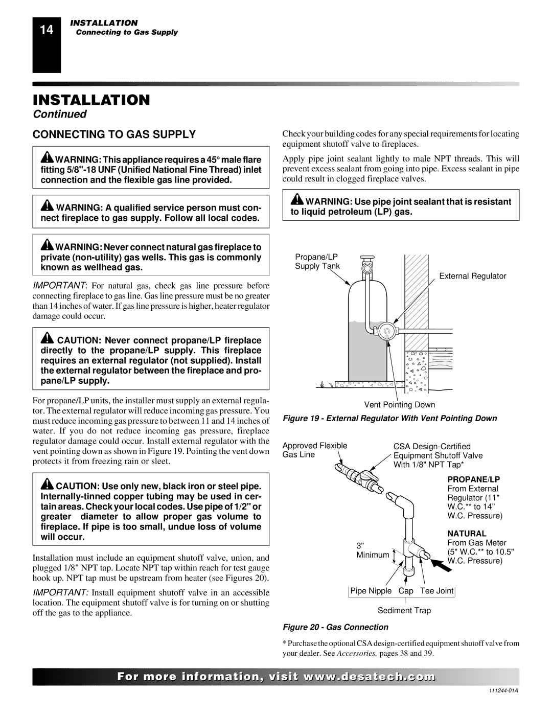
Propane/LP Supply Tank
External Regulator |
For propane/LP units, the installer must supply an external regula- tor. The external regulator will reduce incoming gas pressure. You must reduce incoming gas pressure to between 11 and 14 inches of water. If you do not reduce incoming gas pressure, fireplace regulator damage could occur. Install external regulator with the vent pointing down as shown in Figure 19. Pointing the vent down protects it from freezing rain or sleet.
![]() CAUTION: Use only new, black iron or steel pipe.
CAUTION: Use only new, black iron or steel pipe.
Installation must include an equipment shutoff valve, union, and plugged 1/8" NPT tap. Locate NPT tap within reach for test gauge hook up. NPT tap must be upstream from heater (see Figures 20).
IMPORTANT: Install equipment shutoff valve in an accessible location. The equipment shutoff valve is for turning on or shutting off the gas to the appliance.
Vent Pointing Down
Figure 19 - External Regulator With Vent Pointing Down
Approved Flexible | CSA |
Gas Line | Equipment Shutoff Valve |
| With 1/8" NPT Tap* |
PROPANE/LP
From External
Regulator (11"
W.C.** to 14"
W.C. Pressure)
| NATURAL | |
3" | From Gas Meter | |
(5" W.C.** to 10.5" | ||
Minimum | ||
W.C. Pressure) | ||
|
Pipe Nipple Cap Tee Joint
Sediment Trap
Figure 20 - Gas Connection
*Purchase the optional CSA
![]()
![]()
![]()
![]()
![]() For
For![]()
![]()
![]()
![]()
![]()
![]()
![]()
![]()
![]()
![]()
![]()
![]()
![]() .
.![]()
![]()
![]()
![]() .com
.com![]()
![]()
![]()
![]()
![]()