INSTALLATION
9
INSTALLATION
Continued
BUILT-IN FIREPLACE INSTALLATION
| Actual | Framing |
|
|
|
Height | 26" | 26 7/8" |
Front Width | 26 3/4" | 26 7/8" |
Depth | 14 1/4" | 15 1/4" |
1.Frame in rough opening. Use dimensions shown in Figure 7 for the rough opening. If installing in a corner, use dimensions shown in Figure 8 for the rough opening. The height is 26 7/8" which is the same as the wall opening above.
2.If installing GA3450TA blower accessory, do so at this time. Follow instructions included with blower accessory.
Note: If not installing blower accessory, you may wish to run electrical wiring to your fireplace for future blower installa- tion (see Accessories, pages 36 and 37). Use only approved
15 1/4"
267/8"
267/8"
Figure 7 - Rough Opening for Installing in Wall
435/16"
305/8"
![]() 267/8" 611/4"
267/8" 611/4"
Figure 8 - Rough Opening for Installing in Corner
![]() WARNING: If
WARNING: If
Install fireplace electrical outlet and connect wiring to outlet before connecting to electrical source. The fireplace electrical outlet is included with the GA3450TA blower accessory.
Only use the fireplace electrical outlet supplied with the GA3450TA blower accessory.
Note:A qualified installer should make all electrical connections.
3.Install gas piping to fireplace location. This installation includes an approved flexible gas line (if allowed by local codes) after the equipment shutoff valve. The flexible gas line must be the last item installed on the gas piping.
4.If you have not installed hood, follow instructions on page 4.
5.Carefully set fireplace in front of rough opening with back of fireplace inside wall opening.
6.Attach flexible gas line to fireplace gas regulator. See Con- necting Equipment Shutoff Valve to Heater Control, page 15.
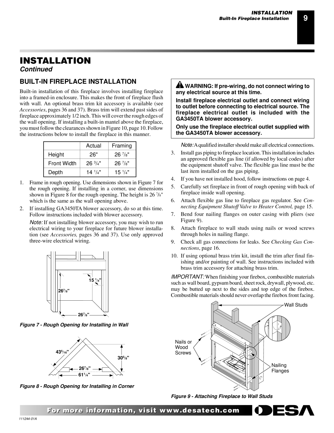
7.Bend four nailing flanges on outer casing with pliers (see Figure 9).
8.Attach fireplace to wall studs using nails or wood screws through holes in nailing flange.
9.Check all gas connections for leaks. See Checking Gas Con- nections, page 16.
10.If using optional brass trim kit, install the trim after final fin- ishing and/or painting of wall. See instructions included with brass trim accessory for attaching brass trim.
IMPORTANT: When finishing your firebox, combustible materials such as wall board, gypsum board, sheet rock, drywall, plywood, etc. may be butted up next to the sides and top edge of the firebox. Combustible materials should never overlap the firebox front facing.
Wall Studs
Nails or
Wood
Screws
Nailing
![]() Flanges
Flanges
Figure 9 - Attaching Fireplace to Wall Studs
For more![]()
![]()
![]() visit www.
visit www.![]()
![]()
![]() .com
.com![]()
![]()
![]()
![]()
![]()